KE2040Instruction Manual Ver2.01,REV04.2003.6.25.pdf - 第47页
1 − 30 1. Feeder bank parts identif ication ( See Figure 1.2.3. 2.) The tape f eeder loaded with taped components, stick f eeder loaded with components in stick s bulk feeder loaded with components in bulk ar e positione…
1 − 29
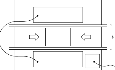
1.2.3 Component feeder
Totally two component feeder banks are provided: one bank is located at the front
and rear of the PWB transport unit respectively. The component supply method
varies depending on the package style of components: tape, bulk, stick or tray.
Components fed by a tape (chip components) or those fed in a stick are mounted on
the feeder bank with using a tape feeder, bulk feeder, stick feeder or stacked stick
feeder, then carried in the main unit. A tray component is fed from a tray holder,
matrix tray changer, or matrix tray server. A tray holder, matrix tray changer or
matrix tray server.can be mounted on the rear of the machine.
When using an overall feeder exchange trolley (option), the feeder bank can be
removed from the main unit of this machine for preparation.
(
)
Figure 1.2.3.1
Feeder banks
PWB
Vision monitor
Rear
Front
PWB transport unit
1 − 30
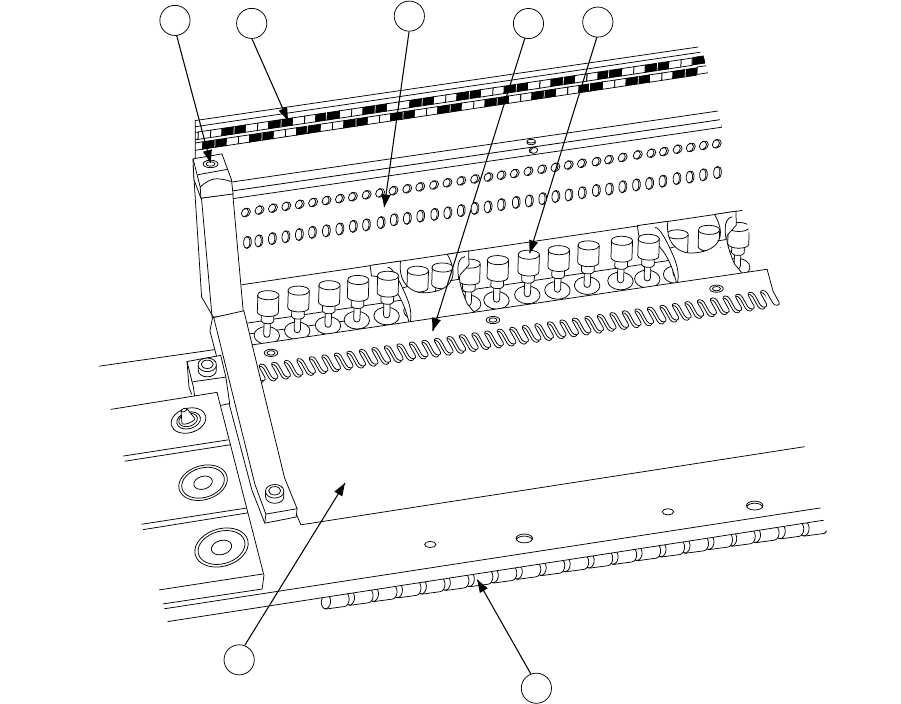
1. Feeder bank parts identification (See Figure 1.2.3.2.)
The tape feeder loaded with taped components, stick feeder loaded with
components in sticks bulk feeder loaded with components in bulk are positioned
and secured by the fixing plate
②
, and lock shaft
④
.
The component feeding device is driven by the drive cylinders
⑤
.
The position label
⑥
is used to determine the position at which each feeder is
installed. You can see LED status of the FPI (optional) to decide where to set
each feeder.
The bank mark
⑦
is the mark for correcting the position of the feeder set.
6
2
4
1
5
7
3
①
Feeder bank
⑤
Drive cylinder
②
Fixing plate
⑥
Position label
③
Fixing plate B
⑦
Bank mark
④
Lock shaft
Figure 1.2.3.2
1 − 31
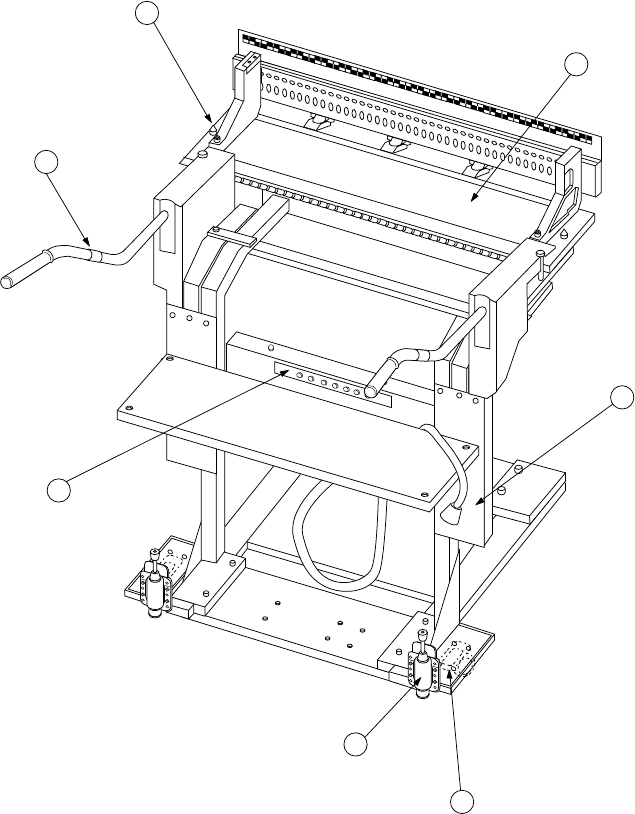
2. Overall feeder exchange trolley parts identification
(See Figure 1.2.3.3.) (Optional)
The Overall feeder exchange trolley is used to remove the feeder bank from the
main unit for easy preparation.
The feeder bank
①
can manually be moved by holding the trolley handle r which
is attached to the floor trolley
③
equipped with casters
②
. Positioning to the
main unit of this machine is carried out with the bank locate pins t on the left and
right. The Overall feeder exchange trolley can be fixed with the trolley stopper
⑥
.
2
1
5
4
7
3
6
①
Feeder bank
⑤
Bank locate pin
②
Casters
⑥
Trolly stopper
③
Floor trolley
⑦
Connector bracket
④
Trolly handle
Figure 1.2.3.3