KE2040Instruction Manual Ver2.01,REV04.2003.6.25.pdf - 第34页
1 − 17 (3) Applicable component Component Name Shape MNLA *1 FMLA St an dar d VCS Optional VCS-1 Optional VCS-2 Optional VCS-3 Package 0603 ○ Square chip resisto r 1005, 1608, 2012, 3216, 3225 (5025, 6432) ○ ○ Network re…
1 − 16
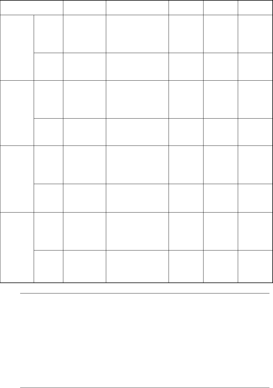
(2) Applicable component (For VCS recognition)
Table 1-1-6-2
Item Partial
recognition
Divided image
recognition
Lead pitch Ball pitch Ball
diameter
Reflective
Minimum:
3 mm x 3 mm
Maximum:
50 mm x 50 mm
Maximum:
50 mm x 150 mm
(when divided into 1 x 3)
Maximum:
74 mm x 74 mm
(when divided into 2 x 2)
Minimum:
0.38 mm
Maximum:
2.54 mm
Minimum:
1.0 mm
Maximum:
3.0 mm
Minimum:
φ 0.4mm
Maximum:
φ 1.0mm
Standard
VCS
(field of view:
54 mm)
Penetrative
Minimum:
9 mm x 9 mm
Maximum:
50 mm x 35 mm
Maximum:
35 mm x 120 mm
(when divided into 1 x 3)
Reflective
Minimum:
3 mm x 3 mm
Maximum:
34 mm x 34 mm
Maximum:
34 mm x 120 mm
(when divided into 1 x 3)
Maximum:
68 mm x 68 mm
(when divided into 2 x 2)
Minimum:
0.3 mm
Maximum:
2.54 mm
Minimum:
0.7 mm
Maximum:
2.0 mm
Minimum:
φ 0.28mm
Maximum:
φ 0.63mm
Optional
VCS-1
(field of view:
37.5 mm)
Penetrative
Minimum:
9 mm x 9 mm
Maximum:
34 mm x 34 mm
Reflective
Minimum:
3 mm x 3 mm
Maximum:
24 mm x 24 mm
Maximum:
24 mm x 72 mm
(when divided into 1 x 3)
Maximum:
48 mm x 48 mm
(when divided into 2 x 2)
Minimum:
0.3 mm
Maximum:
2.54 mm
Minimum:
0.5 mm
Maximum:
2.0 mm
Minimum:
φ 0.2mm
Maximum:
φ 0.63mm
Optional
VCS-2
(field of view:
27 mm)
Penetrative
Minimum:
9 mm x 9 mm
Maximum:
24 mm x 24 mm
Reflective
Minimum:
3 mm x 3 mm
Maximum:
15.5 mm x 15.5
mm
Maximum:
15.5 mm x 46.5 mm
(when divided into 1 x 3)
Maximum:
31 mm x 31 mm
(when divided into 2 x 2)
Minimum:
0.3 mm
Maximum:
2.54 mm
Minimum:
0.35 mm
Maximum:
2.0 mm
Minimum:
φ 0.14mm
Maximum:
φ 0.63mm
Optional
VCS-3
(field of view:
18 mm)
Penetrative
Minimum:
9 mm x 9 mm
Maximum:
15.5 mm x 15.5
mm
Note:
1. The minimum dimensions of a component to be recognized with the VCS are
applied only to a component whose mold dimensions are 7 mm x 7 mm or more.
2. The maximum dimensions of a component to be recognized with the standard
VCS should be within the recognizable range: 52 mm x 52 mm including a
component placement position error and a teaching error which is caused when
the machine picks up the component.
3. The center position of a component should be
±
1 mm or less (in the X and Y
direction) far from the camera center position and the component angle should
be
±
3
°
against the camera center position when the camera is recognizing the
component.
1 − 17
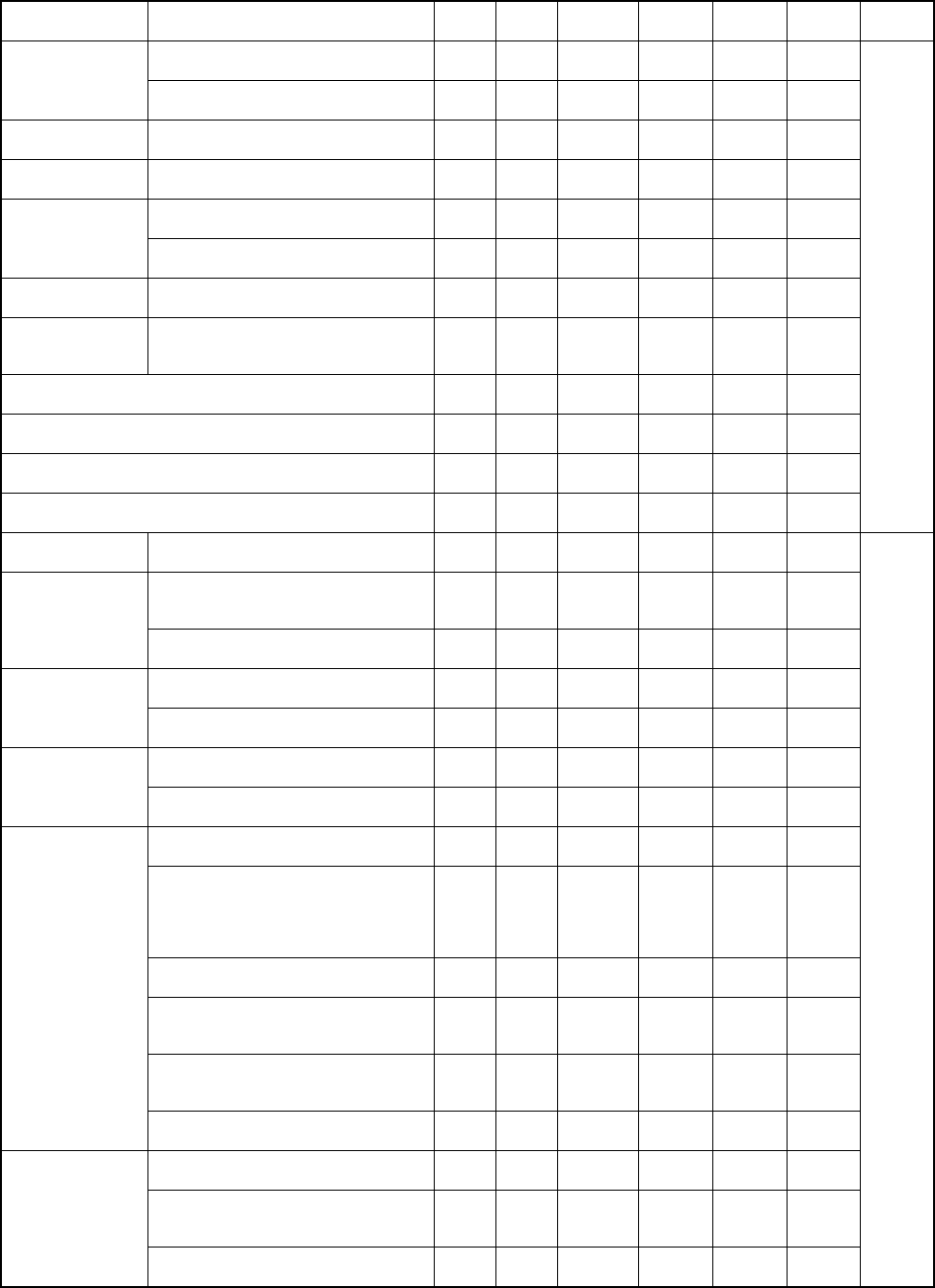
(3) Applicable component
Component
Name
Shape
MNLA
*1
FMLA Standard
VCS
Optional
VCS-1
Optional
VCS-2
Optional
VCS-3
Package
0603
○
Square chip
resistor
1005, 1608, 2012, 3216, 3225
(5025, 6432)
○
○
Network resistor (Excluding SOP, SOJ, PLCC types)
○
○
MELF resistor 1.6 x φ1.0mm, 2.0 x φ1.25mm, 3.5 x
φ1.4mm, 5.9 x φ2.2 mm
○
○
0603
○
○
Laminated
ceramic capacitor
1005, 1608, 2012, 3216, 3225, 4532,
5750 (5632)
○
○
Tantalum chip
capacitor
3216, 3528, 6032, 7343
○ ○
Aluminum
electrolytic
capacitor Height:
Height: more than 6 mm, but 10.5
mm or less
○
○ ○
Chip film capacitor
○
○
Variable trimmer capacitor, Chip potentiometer, trimmer
○
○
Chip ferrite beads
○
○
Chip inductor
○
○
Tape
SOT molded part 1608/2012, SOT-23,
SOT-89, SOT-143, SOT-223
○
○
8-, 14-, 16-, 18-, 20-, 24- and 28-pins
Length of a diagonal line: 31.5 mm or
less
○ ○ ○
SOP
32, 40-pin
○ ○
16, 18, 20, 24, 26, 28, 32-pin
○
○ ○
SOJ
40-pin
○ ○
18, 20, 22, 28 (Square),
28 (Rectangle), 32, 44-pins
○
○ ○
PLCC
52, 68, 84-pins
○ ○
Pitch 0.65/0.8/1.0
Dimensions: 20 mm x 20 mm or less
○
○ ○
Pitch: 0.65/0.8/1.0
Dimensions: more than 20 mm x 20
mm or 23.5 mm (length) x 11 mm
(width), but 33.5 mm x 33.5 mm or
less
○ ○
Pitch: 0.4/0.5/0.6/0.8/1.0
Dimensions: 50 mm x 50 mm or less
○
Pitch: 0.3
Dimensions: more than 24 mm x 24
mm, but 33.5 mm x 33.5 mm or less
○
Pitch: 0.3
Dimensions: more than 16 mm x 16
mm, but 24 mm x 24 mm or less
○ ○
QFP, BQFP
Pitch: 0.3
Dimensions: 16 mm x 16 mm or less
○ ○ ○
Dimensions: 20 mm x 20 mm or
less , 23.5 mm(L) x 11 mm(W) or less
○
○ ○
Dimensions: 20 mm x 20 mm , more
than 23.5 mm(L) x 11 mm(W), but
33.5 mm x 33.5 mm or less
○ ○
BGA
Dimensions: more than 33.5 mm x
33.5 mm, but 50 mm x 50 mm or less
○
Tape
Stick
Tray
*1 : applicable to a KE-2020
Table 1-1-6-3

1 − 18
Component Name Shape
MNLA
*1
FMLA Standard
VCS
Optional
VCS-1
Optional
VCS-2
Optional
VCS-3
Package
Pitch: 0.65 or more
Dimensions: 20 mm x 20 mm or
less, or 23.5 mm (length) x 11 mm
(width) or less
Recognizable with laser
○
○ ○
Pitch: 0.65 or more
Dimensions: 20 mm x 20 mm or
less, or 23.5 mm (length) x 11 mm
(width) or more but 33.5 mm x 33.5
mm or less
Recognizable with laser
○ ○
Pitch: 0.4 or more
Dimensions: 150 mm x 150 mm or
less
Recognizable with the VCS
○
Pitch: 0.3
Dimensions: more than 24 mm x
24 mm, but 33.5 mm x 33.5 mm or
less
Recognizable with the VCS
○
Pitch: 0.3
Dimensions: more than 16 mm x
16 mm, but 24 mm x 24 mm or less
Recognizable with the VCS
○ ○
Unidirectional lead
connector
Bidirectional lead
connector
Pitch: 0.3
Dimensions: 16 mm x 16 mm or
less
Recognizable with the VCS
○ ○ ○
Pitch: 0.65 or more
Dimensions: 20 mm x 20 mm or
less, or 23.5 mm (length) x 11 mm
(width) or less
Recognizable with laser
○
○ ○
Pitch: 0.65 or more
Dimensions: 20 mm x 20 mm or
less, or 23.5 mm (length) x 11 mm
(width) or more but 33.5 mm x 33.5
mm or less
Recognizable with laser
○ ○
Pitch: 0.5 or more
Dimensions: 150 mm x 150 mm or
less
Recognizable with the VCS
○
Pitch: 0.3
Dimensions: more than 24 mm x
24 mm, but 33.5 mm x 33.5 mm or
less
Recognizable with the VCS
○
Pitch: 0.3
Dimensions: more than 16 mm x
16 mm, but 24 mm x 24 mm or less
Recognizable with the VCS
○ ○
IC socket
Pitch: 0.3
Dimensions: 16 mm x 16 mm or
less
Recognizable with the VCS
○ ○ ○
Dimensions: more than 24 mm x
24 mm, but 33.5 mm x 33.5 mm or
less
○
Dimensions: more than 16 mm x
16 mm, but 24 mm x 24 mm or less
○ ○
FBGA
Dimensions: 216 mm x 16 mm or
less
○ ○ ○
Tape
Stick
Tray
*1 : applicable to a KE-2020