KE2040Instruction Manual Ver2.01,REV04.2003.6.25.pdf - 第445页
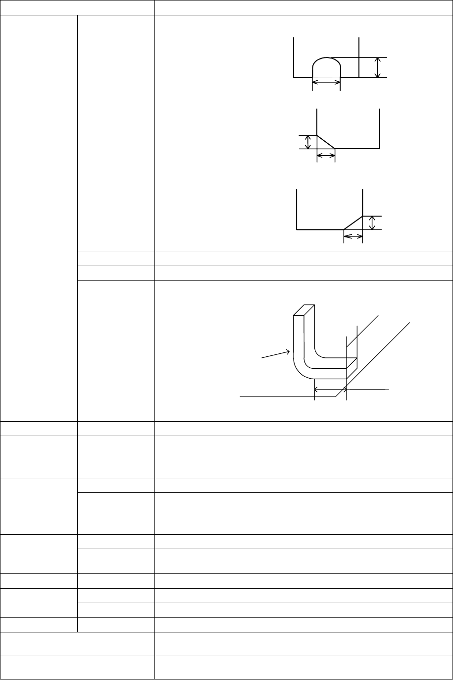
5 − 55 L L L L W W W W L L L L W W W W L L L L W W W W Setting item Description Cut shape Sel ect a c ut shape of a lead: - Fl at - U-s hape cut - Cut at t he lower left c orner - Cut at t he lower right corner Cut lengt…
5 − 54
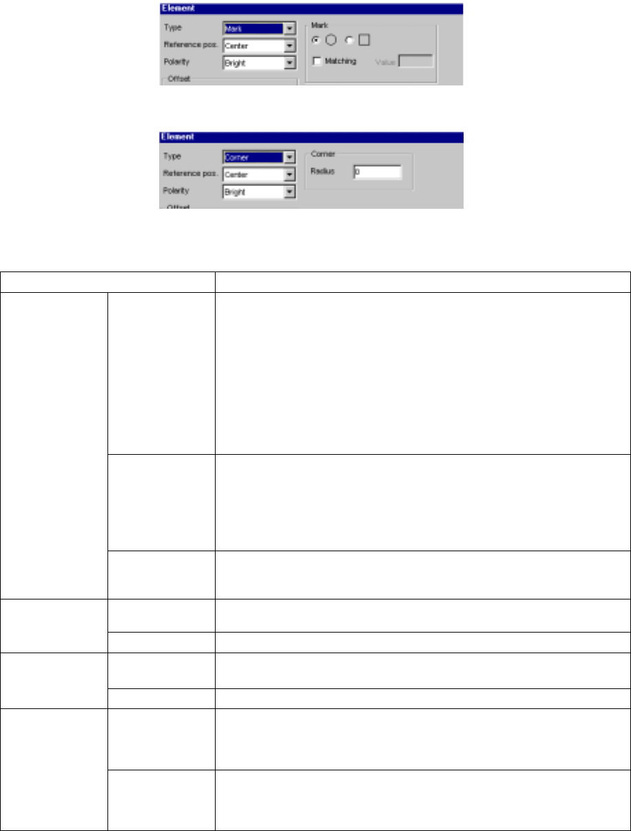
(5) When you select “Mark”
(6) When you select “Corner”
• Detailed description of each setting item
Setting item Description
Type Select an element type according to the “Dimension” setting as shown below:
1D
- Outer Lead (referred from the top view)
- Inner Lead (referred from the top view)
1D and 2D
- Ball (referred from the bottom view)
- Land (referred from the bottom view)
- Column (referred from the bottom view)
Point
- Mark (referred from the bottom view)
- Side (referred from the top view)
- Corner (referred from the top view)
Reference pos.
(position)
(A displayed
value is set, and
fixed according to
the “Type”
setting.)
Select the element reference position:
- Center: center of an element (selected when “Ball”, “Land”, “Mark” or
“Marginal area” is selected)
- Center of the bottom side: (selected when “Outer Lead”, “Inner Lead” or
“Side” is selected) (for a lead component)
- Lower left position: (selected when “Corner” is selected)
Element
Polarity Select the brightness of an element:
- Bright
- Dark
X, Y, Z and Theta Set an offset if the coordinates set in the “Element Group” screen should be
offset further. (Not used)
Offset
Tolerance Set the allowable offset range. (Not used)
Size Enter the size of an element: dimensions of a lead.
- “X” indicates the width and “Y” indicates the length.
Element size
Tolerance Set the allowable size range. (Not used)
Profile Set the lead type:
- Flat
- Gullwing
- J-bent
Outer Lead/Inner
Lead
Coating Select coating applied to a lead:
- Bare (No plating)
- Gold-plating
- Solder-plating
5 − 55
L
LL
L
W
WW
W
L
LL
L
W
WW
W
L
LL
L
W
WW
W
Setting item Description
Cut shape Select a cut shape of a lead:
- Flat
- U-shape cut
- Cut at the lower left corner
- Cut at the lower right corner
Cut length Enter the length of a cut portion of a lead (L).
Cut width Enter the width of a cut portion of a lead (W).
Lead size Enter the length and width of a foot portion of a lead.
Tolerance
Set the tolerance of the footprint size (width and height).
Ball Inspection –
Diameter, area,
ball/no ball,
diameter average
Check off the check box of the target item to be inspected.
Set the inspection ratio of the check item to be checked.
Mark ID
Set the shape ID according to the mark shape.
Land
Inspection –
Diameter, area,
ball/no ball,
diameter average
Check off the check box of the target item to be inspected.
Set the inspection ratio of the check item to be checked.
Mark ID
Set the shape ID according to the mark shape.
Mark
Matching
Check off the check box if it is a target for matching inspection.
Set the mark correlation matching inspection value.
Hole Mark ID
Set the shape ID according to the mark shape.
Mark ID
Set the shape ID according to the mark shape.
Column
Height
Set the column height.
Corner Corner
Set the corner R value.
OK Registers data and displays the “Element Group” or “Extended Array” screen
again.
Cancel Cancels data registering and displays the “Element Group” or “Extended Array”
screen again.
Length
Width
Lead
Board
5 − 56
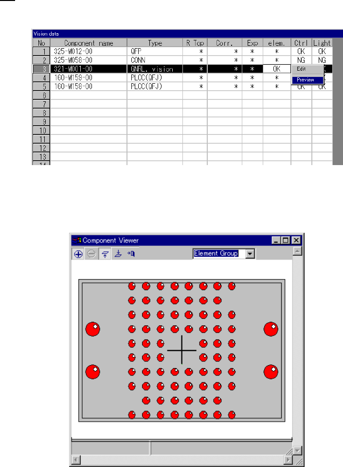
3.6 General Vision Component Preview Function
If element data is completed, you can select Preview.
When you select Preview, the following dialog appears.
How to use Component Viewer is described in “5.2.4.6 Component Viewer”.