KE2040Instruction Manual Ver2.01,REV04.2003.6.25.pdf - 第55页
1 − 38 1.2.7 OCC parts identification (1) Off set correction camera The machine is equipped with a coaxial light and polar izing f ilter as t he standard devices. The cam era detects a BOC mark and correct s the detected…
1 − 37
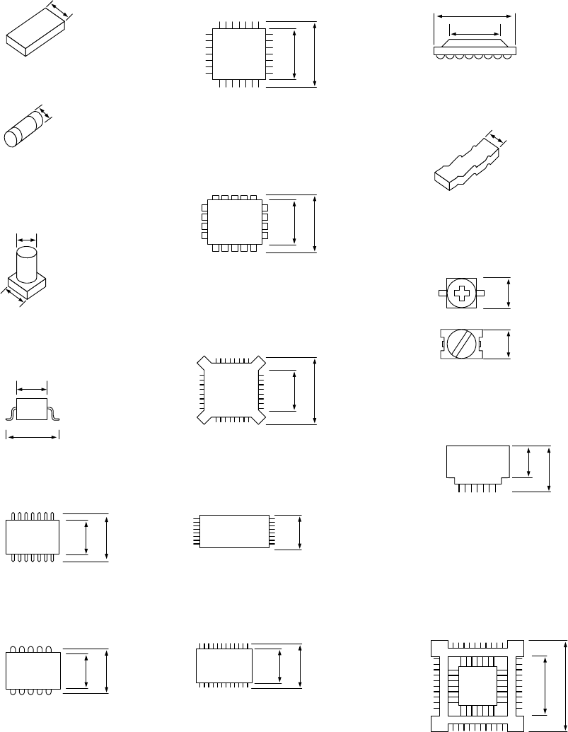
(3) Minimum component width (D) of each component.
!1
A
D
A
D
W
D
A
D = A
A
D
A
D
A
D
A
D
D
A
D = A
A
A
A
D = A
AA
D = A
A
D
A
D
A
D
① Square chip
② MELF
③ Aluminum
electrolytic capacitor
D = A + 0.5mm
④ SOT
⑤ SOP
⑥ SOJ
⑦ QFP ⑫ BGA
⑧ PLCC
⑨ BQFP
⑩ TSOP
⑪ TSOP2
⑬ Network resistor
⑭ Trimmer
⑮ One-way lead connector
⑯ Gull wing socket
J lead socket
Socket with bumper
1 − 38
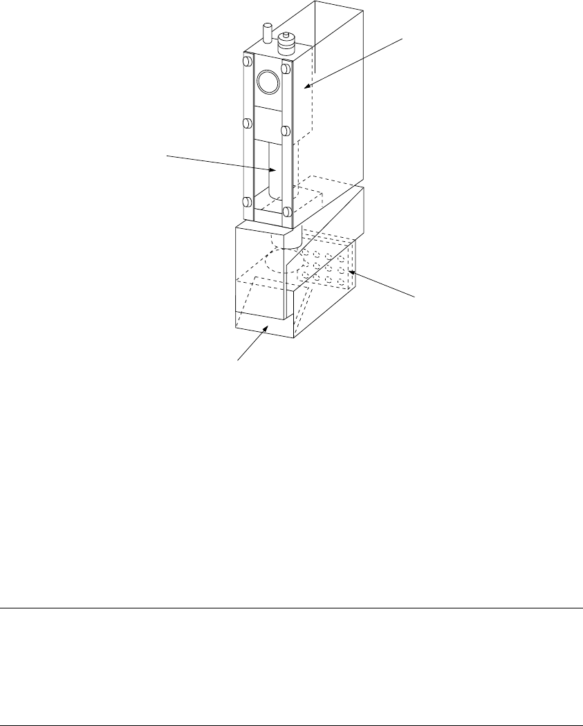
1.2.7 OCC parts identification
(1) Offset correction camera
The machine is equipped with a coaxial light and polarizing filter as the standard
devices. The camera detects a BOC mark and corrects the detected mark
automatically.
① OCC camera
② OCC lens
③ Illumination LED board
④ Mirror box
Figure 1.2.7.1
Adjusting the polarizing filter
1) Place a white ceramic board on the calibration block, then move the camera over
this board.
2) Loosen the screw to turn the filter holder to the right and left. When the screen
becomes brightest, fix the screw.
①
④
③
1 − 39
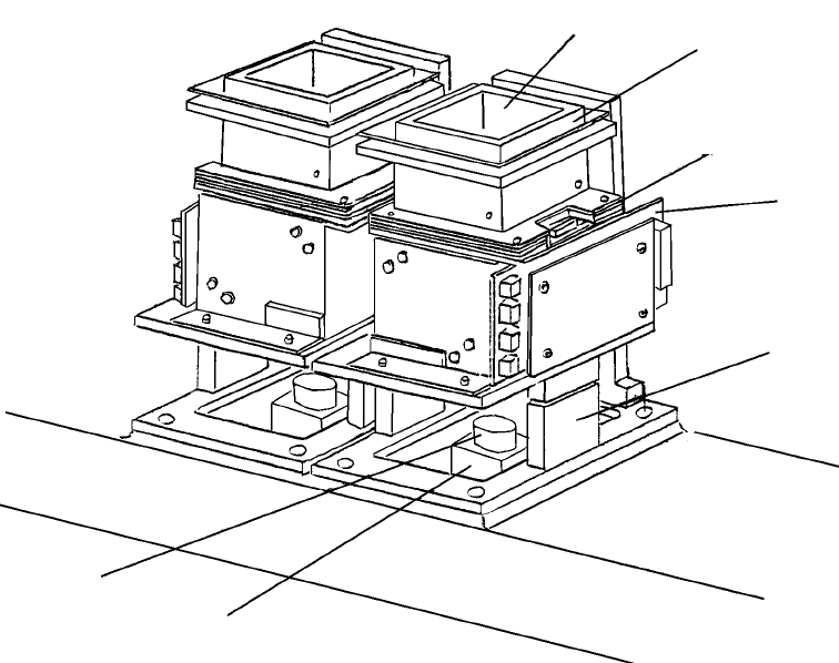
1.2.8 VCS parts identification
The VCS recognizes a component with the following devices: reflective/penetrative
lights, three-dimension movable light and coaxial light, then places on a board a
component such as a QFP, BGA, CSP and connector.
Figure 12.8.1 VCS unit parts identification
① LED board (for the penetrative light)
② LED board (for the side light)
③ LED board (for the bottom light)
④ LED board (for the coaxial light)
⑤ VCS lens
⑥ VCS camera
⑦ Air cylinder
①
②
③
④
⑦
⑥
⑤