KE2040Instruction Manual Ver2.01,REV04.2003.6.25.pdf - 第431页
5 − 87 5) Corner element A corner element is indicated in red. Fig. 5.2. 4.6.4-5 Example of Corner Element Screen Di splay Resizing the “Component View er” dial og screen The “Component Viewer” screen can be resiz ed. Ev…
5 − 86
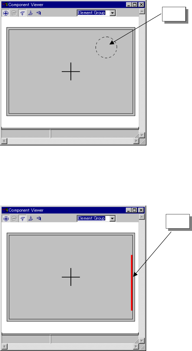
3) Mark element
A mark element is indicated as a dotted line circle or rectangle.
Fig. 5.2.4.6.4-3 Example of Mark Element Screen Display
4) Side element
A side element is indicated as a red line.
Fig. 5.2.4.6.4-4 Example of Side Element Screen Display
Mark
Side
5 − 87
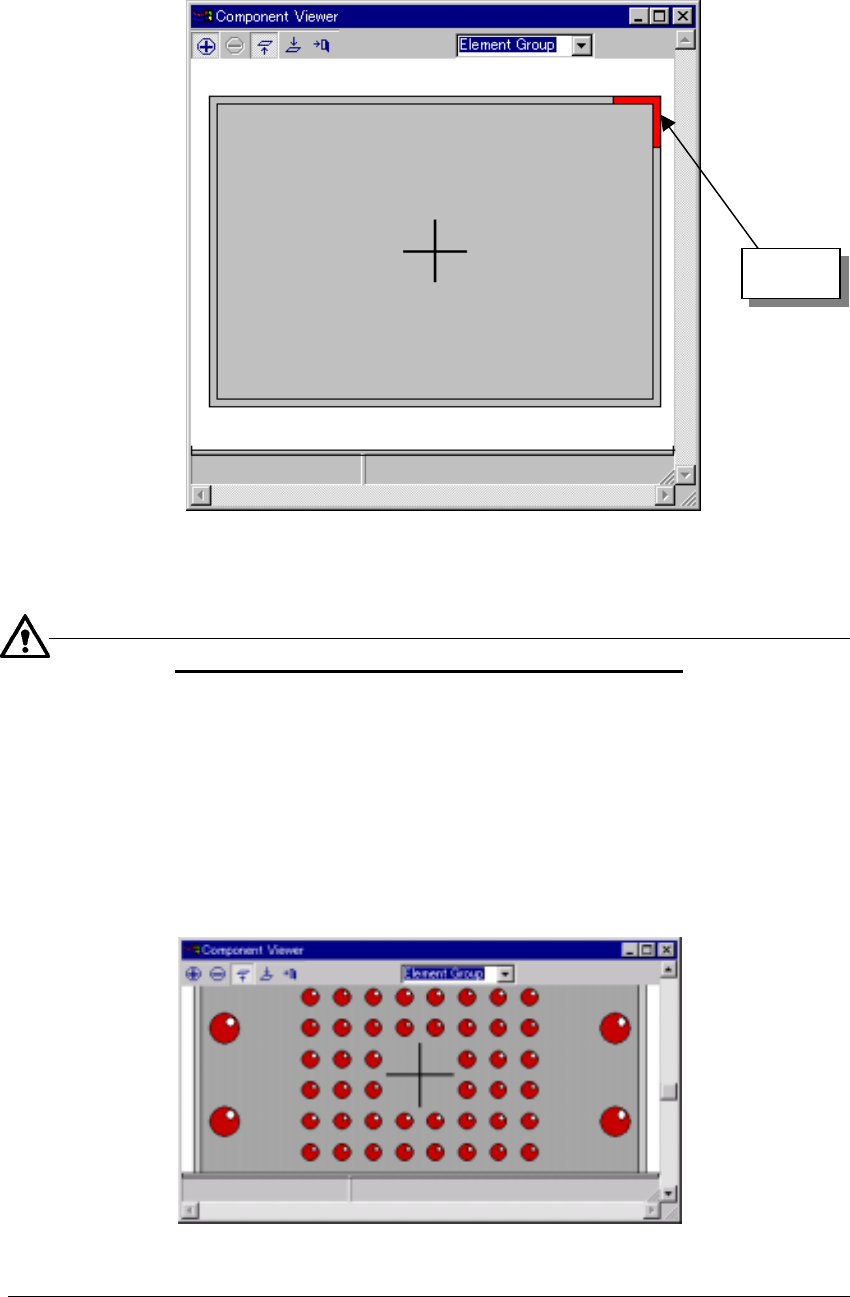
5) Corner element
A corner element is indicated in red.
Fig. 5.2.4.6.4-5 Example of Corner Element Screen Display
Resizing the “Component Viewer” dialog screen
The “Component Viewer” screen can be resized. Even if the screen is resized, the
dimensions of the displayed component remain without change.
− In the status where the scroll bar is displayed by zooming in the component,
resize the screen. When the screen is enlarged, the component in a larger
range can be seen.
− When the screen is contracted, a part of the component may be invisible.
− Resize processing changes the screen size on the basis of the center of the
currently displayed screen.
Fig. 5.2.4.6.4-6 Example of Resize Display Screen
Corner
5 − 88
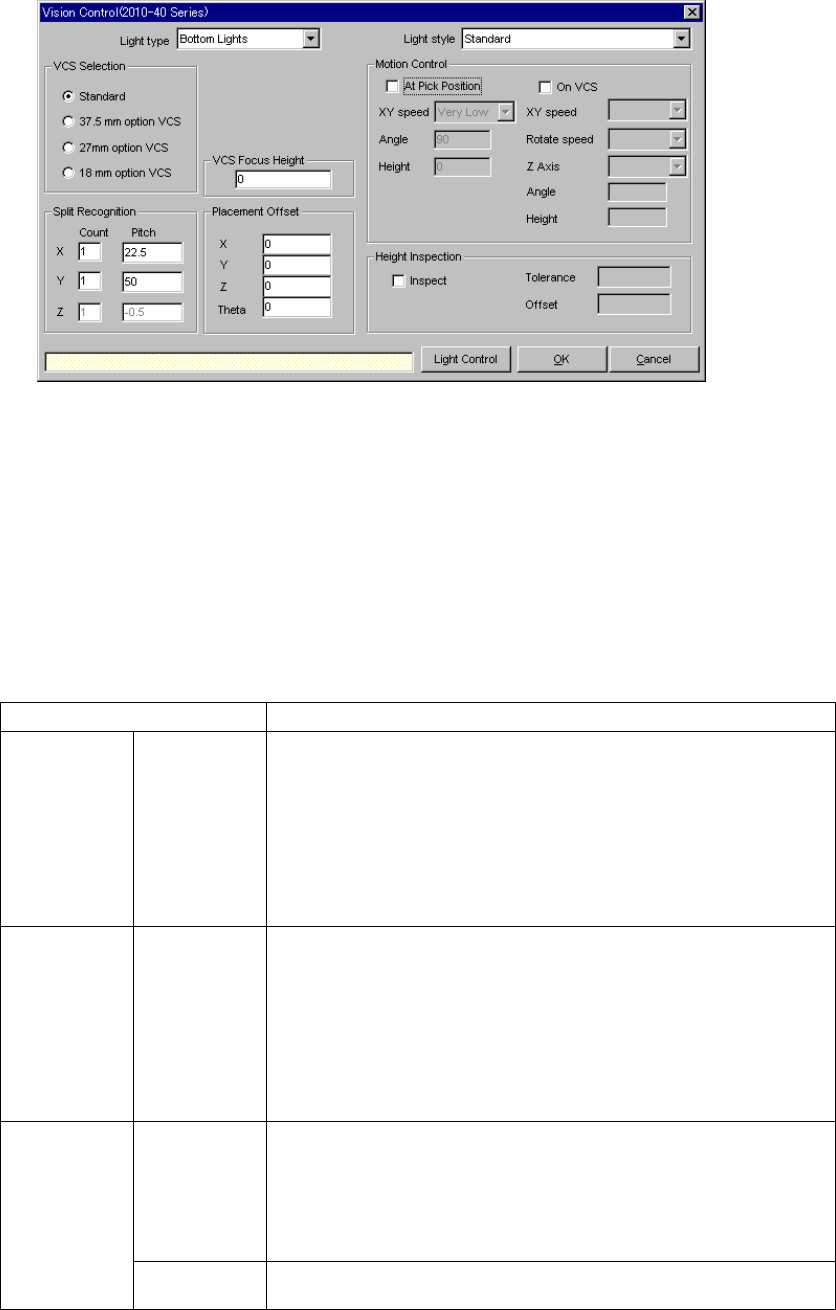
5.2.5 Ctrl (Control)
When you click the [Edit] command displayed in the “Ctrl” field, the following screen
appears.
• Set the light used for recognizing divided image in the following order:
1. Set a VCS used for recognizing a component.
2. Determine the division recognition.
3. Specify the Light type and Light style (when the Light type is “Back lights” or
“Side lights”).
4. Set the other items.
• Detailed description of each setting item
Item Description
Light type Select the light type:
- Bottom Lights
This type of light is a red light consisting of three light blocks: coaxial light
(half mirror light), bottom light and red side light (upper and lower stages).
- Back Lights
This type of light is a green light used for using the shade of a component
to center the component that cannot be illuminated with the back light.
- Side Lights
This is a light (normally blue light) used for recognizing a solder ball of a
BGA (FBGA).
Light style Select the sub light type.
Bottom
- Standard
- CBGA
- LGA
Side
- Red side light
- Red side light equipped with a pop-up light
- Blue side light
- Blue side light equipped with a pop-up light
Count Set the number of divisions of image in the X, Y and Z directions.
The number of divisions in each direction is:
X: 1 to 2
Y: 1 to 3
Z: 1 to 2
(See Section 5.2.5.1 “Applicable component dimensions during division
recognition”.)
Split
recognition
Pitch Specify the distance over which a VCS moves. The value range varies
depending on the selected VCS.