KE2040Instruction Manual Ver2.01,REV04.2003.6.25.pdf - 第391页
5 − 28

5 − 27
(C) Center recognition
Recognition conditions
① Components whose ratio of width to length is 1:2 or more
② Components whose side portion is 0.3 mm or more (The inside of a side
may be hollow at imaging.)
When the above conditions are satisfied, center recognition is enabled.
Note: Concavity and convexity may exit on the component outline. However, they
have an effect on the center position and inclination.
In this case, adjust the placement data, etc.
4) Recognition component examples
The components to be supported by the component outline recognition function
are those whose shapes are close to a rectangle or regular square. The edges
forming an outline should be 0.3 mm or more.
* In the component drawing shown in the following table, the black/white is
reversed unlike the reality.
Table 5.2.3.11-1 Recognition Components Table

5 − 28
5 − 29
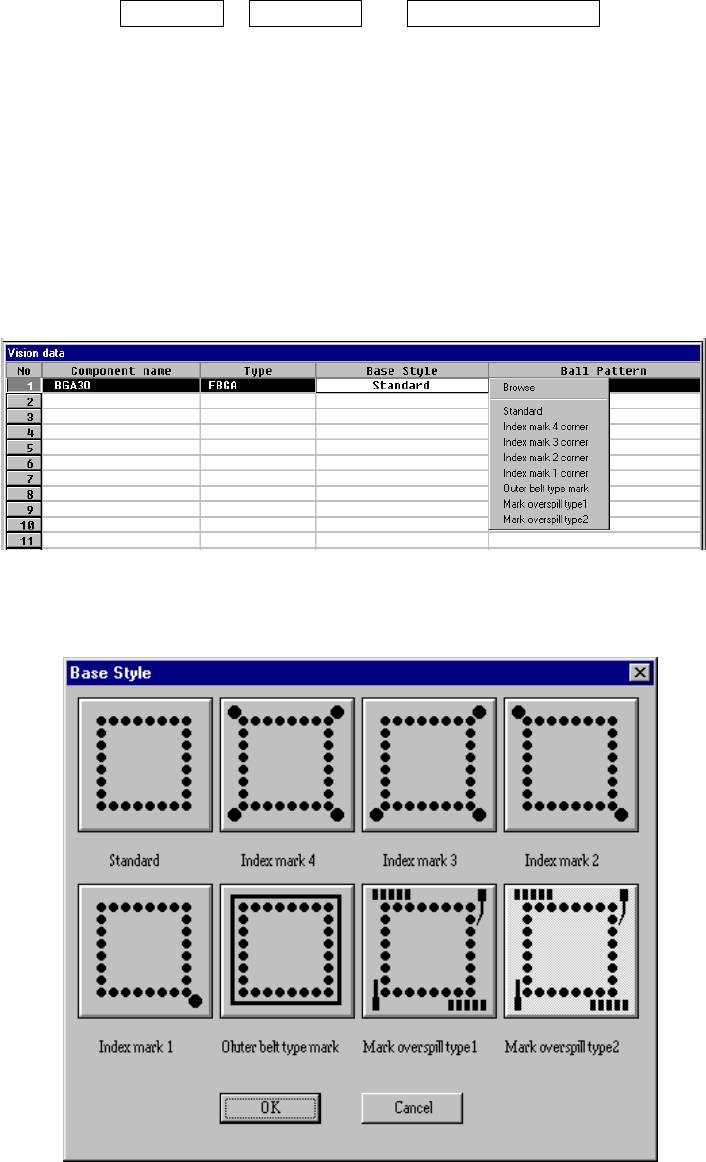
⑫ Base Style
Set the base style of a BGA component. This item is available only when you
select “All balls” or “All land” at the “Contrast” setting item.
A base style is combined with a ball pattern, then used as a recognition
pattern.
Base style + Ball pattern → Recognition pattern
• How to set
When you click this setting item with the right button, the selection
pop-up menu appears on the screen.
− When you select Browse
Figure 6.7-2-18 (b) “Base Style” browser dialog box