KE2040Instruction Manual Ver2.01,REV04.2003.6.25.pdf - 第381页
5 − 18 ② V ision data of a lead connector component W hen you select “O nly the both ends lead” or “ Both ends lead exclusion” in the “View Field” f ield f or a unidirect ional lead connector , bi-direct ional lead conne…
5 − 17
Figure 5.2.2.2.2-2 Example 1
−
−−
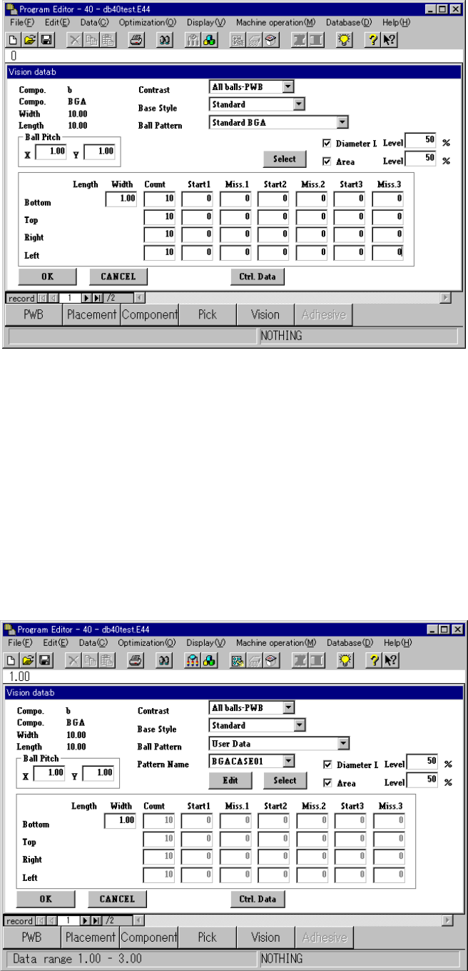
− When you select “User Data” in the “Ball Pattern” field, the ball pattern edit
function starts up if you have not set the corresponding user data yet.
Otherwise, the ball pattern name appears below the <Edit> and <Select>
buttons. (See Figure 5.2.2.2-3 “Example 2.”)
If you click the <Edit> button when another pattern is selected, the ball pattern
edit function starts up also. How to operate this function is the same as that
when you start it up on the Vision list screen.
Figure 5.2.2.2.2-3 Example 2
5 − 18
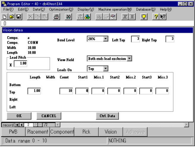
② Vision data of a lead connector component
When you select “Only the both ends lead” or “Both ends lead exclusion” in
the “View Field” field for a unidirectional lead connector, bi-directional lead
connector or Z lead connector, the “Left Top” and “Right Top” edit boxes
appear on the screen, in which you can enter the number of leads located on
the upper left-hand, upper right-hand, lower left-hand and lower right-hand
sides.
(See Figure 5.2.2.2.4 “Example 3.”)
Enter the number of leads located on the upper left-hand and right-hand sides
for a unidirectional lead connector, or that on the lower left-hand, upper
right-hand, lower left-hand and lower right-hand sides for a bi-directional lead
connector or Z lead connector.
Figure 5.2.2.2.4 Example 3
5 − 19
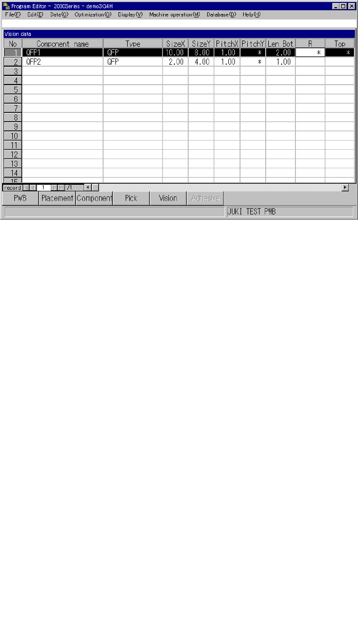
5.2.3 Detailed description of operation
When you invoke Vision data for the first time, data appears in the “Component
name”, “Type”, “SizeX” and “SizeY” cells only.
Figure 5.2.3.1 Vision data initial screen
(1) How to set the items
① Component name
A component name entered on the Placement data screen appears in this cell.
② Type
A component type entered on the Component data screen appears in this cell.
③ Size X
The width of a component, which was entered on the Component data screen,
appears in this cell.
④ Size Y
The length of a component, which was entered on the Component data screen,
appears in this cell.
⑤ 1) PitchX
Enter the horizontal pitch between two consecutive leads (balls) from the
formula bar. The input range varies depending on the component type.
2) PitchY
Enter the vertical pitch between two consecutive leads (balls) from the
formula bar. The input range varies depending on the component type.
Figure 5.2.3.2 Pitches applied to each component type
Ball pitch
(Normal assignment)
Ball pitch
(Stagger assignment)