KE2040Instruction Manual Ver2.01,REV04.2003.6.25.pdf - 第414页
5 − 70 ⑤ Element siz e Ent er the size of an element. Since the shape of a rectang ular land is still a sq uare, ent er the same value to both the “W idt h” and “Leng th” f ields. - I n the example, the diam eter is assu…
5 − 69
⑥ Missing Elements
In the example, there is missing balls (lands) on the first element group. If
there is/are a missing ball(s)/land(s), specify this setting item also in the same
manner as that of a BGA/FBGA.
Up to four blocks of missing balls/lands can be specified per element group.
To specify a block, set the first missing ball/land position of the column and
row respectively and the number of lines having missing balls/lands located
continuously in the same manner when you set those of a BGA/FBGA
component.
- If there is no ball/land on three columns from the second column and no
balls/lands on two rows from the fourth row, enter values as shown below:
“Start” of the “Column” field: 2
“Count” of the “Column” field: 3
“Start” of the “Row” field: 4
“Count” of the “Row” field: 2
Note: If there is no ball/land at five or more portions, divide the element
group further, then define those divided element groups.
♦ - Here, you have finished setting an element group.
- Next, define a recognition element of this element group.
Only one element can be defined per element group. Even though you
define two or more elements, they are handled as “invalid”.
Click the <Add> button in the “Element” setting field.
3. “Element” screen
① Type
You can specify a ball or land as an element type of ball components. This
version does not support a column.
When you specify a land as an element, you can select a circular land or
rectangular land.
For a bump, specify “Ball” as an element type from the “Type” combo box.
For an electrode that is flat entirely, specify “Land”.
- In the example, a ball is used. Select “Ball” from the “Type” combo box.
② Reference pos. (position)
The reference position of a ball/land element is the center of an element.
- Select “Center of an element” from the “Reference pos.” combo box.
③ Polarity
This item specifies the brightness of the shot image of an element.
- Normally, the light that illuminates a ball/land element brightly is used for
ball components. Select “Bright” from the “Polarity” combo box.
Note: Since a CBGA illuminates the surroundings of a ball, select “Dark”.
④ Offset
Normally, this setting item is not used. Enter “0” to each field of this item.
5 − 70
⑤ Element size
Enter the size of an element.
Since the shape of a rectangular land is still a square, enter the same value to
both the “Width” and “Length” fields.
- In the example, the diameter is assumed to be 0.5 mm. Enter the following
values.
Width: 0.5
Length: 0.5
- Normally, the “Tolerance” setting item is not used. Do not change this field
setting “0”.
⑥ Ball/Land
For a land, you can select a circular land or rectangular land. Click the
corresponding check box.
- In the example, a ball element is used, so these check boxes do not appear
on the screen.
⑦ Inspection
Click the check box of the item to be inspected.
The check items “Diameter” and “Area” are the same as those for a
BGA/FBGA. Specify the corresponding check level in %. The default value
for each check level is 50 %.
Specify the check level of the “Ball exist?” check in %. also However, the
percentage indicates the internal evaluated characteristics. Normally use the
default value, “30 %”. For a land element, this item is handled as “invalid”
even though you specify this item, and the machine does not perform the
check to see if a ball exists on a component.
- Normally, the setting item “Average diameter” is not used.
- If you perform the “Diameter”, “Area” and “Ball exist?”checks with specifying
the default value respectively, the following values are used for each check:
Inspection Area: 50 % (default)
Diameter: 50 % (default)
Ball exist: 30 % (default)
Average diameter:
You have to click each check box only.
• Here, you have finished entering data on an element. When you click the
<OK> button at the lower right corner, the “Element Group” screen reappears.
You have finished defining the first element group. When you click the <OK>
button at the lower right corner, the “Extended Vision” screen reappears.
If you have another element group to be defined, click the <Add> button again
to enter data on the element group. In the example, there are four element
groups. Define four element groups.
When you finish defining all element groups, click the <OK> button at the lower
left corner to finish entering the Extended vision data.
5 − 71
All of the entered data is shown below.
Figure 5.2.4.4.17
Element
Group
Name
First
element
position
Layout
inspectio
n
(Dimension)
Missing
Elements
Element
Element
Offset
Element size (Shape) Inspection
ELG0001 X: -6.0
Y: -5.0
Z: 0
θ: 0
Tolerance:
All set to “0”.
0%
√ 2D
Count of Column: 9
Pitch: 1.5
Count of Row: 6
Pitch: 1.27
Tolerance: 0
Column
Start: 22
Count: 3
Row
Start: 4
Count: 2
Type: Ball
Reference pos.:
Center of element
Polarity: Bright
Offset: all
set to “0”.
Tolerance:
all set to “0”.
Element size
Width: 0.5
Length: 0.5
Tolerance:
all set to “0”.
(Since an element
is a ball, the
selection screen
does not appear
which allows you
to select a circular
or rectangular
shape.)
Diameter:
50
Area: 50
Ball exist?:
30
Average
diameter: 0
ELG0002 X: -8.25
Y: 1.5
Z: 0
θ: 0
Tolerance:
All set to “0”.
0%
√ 2D
Count of Column:
12
Pitch: 1.5
Count of Row: 2
Pitch: 1.0
Tolerance: 0
Type: Ball
Ref
erence pos.:
Center of element
Pol
arity: Bright
Offset: all
set to “0”.
Tolerance:
all set to “0”.
Element size
Width: 0.5
Length: 0.5
Tolerance:
all set to “0”.
(Since an element
is a ball, the
selection screen
does not appear
which allows you
to select a circular
or rectangular
shape.)
Diameter:
50
Area: 50
Ball exist?:
30
Average
diameter: 0
ELG0003 X: -7.5
Y: 4.0
Z: 0
θ: 0
Tolerance:
All set to “0”.
0%
√ 2D
Count of Column: 5
Pitch: 1.5
Count of Row: 4
Pitch: 1.0
Tolerance: 0
Type: Ball
Ref
erence pos.:
Center of element
Pol
arity: Bright
Offset: all
set to “0”.
Tolerance:
all set to “0”.
Element size
Width: 0.5
Length: 0.5
Tolerance:
all set to “0”.
(Since an element
is a ball, the
selection screen
does not appear
which allows you
to select a circular
or rectangular
shape.)
Diameter:
50
Area: 50
Ball exist?:
30
Average
diameter: 0
ELG0004 X: 1.5
Y: 5.5
Z: 0
θ: 0
Tolerance:
All set to “0”.
0%
√ 2D
Count of Column: 5
Pitch: 1.5
Count of Row: 3
Pitch: 0.8
Tolerance: 0
Type: Ball
Ref
erence pos.:
Center of element
Pol
arity: Bright
Offset: all
set to “0”.
Tolerance:
all set to “0”.
Element size
Width: 0.5
Length: 0.5
Tolerance:
all set to “0”.
(Since an element
is a ball, the
selection screen
does not appear
which allows you
to select a circular
or rectangular
shape.)
Diameter:
50
Area: 50
Ball exist?:
30
Average
diameter: 0
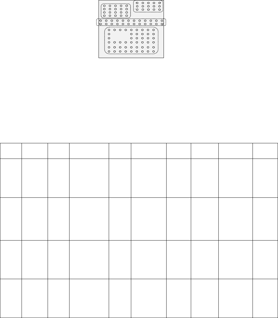
Bottom View
Third element group
(X, Y): (-7.5, 4.0) mm
Pitch of Column: 1.5 mm, Count: 5
Pitch of Row: 1.0 mm, Count: 4
Missing Elements: none
Ball diameter: 0.5 mm
Inspection: Area 50 %
Diameter 50 %
Ball exist? 30 %
Forth element
(X, Y): (1.5, 5.5) mm
Pitch of Column: 1.5 mm, Count: 5
Pitch of Row: 0.8 mm, Count: 3
Missing Elements: none
Ball diameter: 0.5 mm
Inspection: Area 50 %
Diameter 50 %
Ball exist? 30 %
Second element
(X, Y): (-8.25, 1.5) mm
Pitch of Column: 1.5 mm, Count: 12
Pitch of Row: 1.0 mm, Count: 2
Missing Elements: none
Ball diameter: 0.5 mm
Inspection: Area 50 %
Diameter 50 %
Ball exist? 30 %
First element
(X, Y): (-6.0, -5.0) mm
Pitch of Column: 1.5 mm, Count: 9
Pitch of Row: 1.27 mm, Count: 6
Missing Elements:
Start 2 Count 3
Start 4 Count 2
Ball diameter: 0.5 mm
Inspection: Area 50 %
Diameter 50 %
Ball exist? 30 %