KE2040Instruction Manual Ver2.01,REV04.2003.6.25.pdf - 第320页
4 – 210 4.12.3 Checking a component w ith vision recognition This check attaches a component to a head actually to check to see if a component can be centered with the vision recognition f unction. 4.12.3.1 Checking a co…
4 – 209
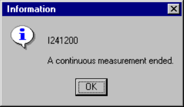
(4) When continuous measurement finishes
When the system finishes measuring all components which satisfy the specified
conditions, the following dialog box appears on the screen.
Figure 4.12.2.4.3.7 “Information” - End of continuous measurement dialog box
4 – 210
4.12.3 Checking a component with vision recognition
This check attaches a component to a head actually to check to see if a component
can be centered with the vision recognition function.
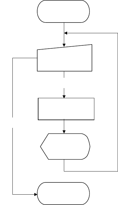
4.12.3.1 Checking a component with vision recognition
The operation flow for checking a component with the vision recognition function is
shown below.
Figure 4.12.3.1.1 Operation flow for checking a component with vision recognition
in Single check mode
4.12.3.2 Methods for checking a component with vision recognition
The system exercises a series of controls over the vision centering function according
to the settings of Component data, and checks to see if no error occurs.
Execution of check
(on the dialog box)
Start of check with
vision recognition
Check
Check with vision
recognition
Display of the
result (on the
dialog box)
End of check with
vision recognition
End
4 – 211
4.12.3.3 Operations done during checking a component with vision recognition
① Head used to pick up a component
The system automatically selects a head that is used to pick up a component.
It also selects a nozzle already attached on a head rather than one not attached
so that nozzles can be replaced less frequently.
However, the system may use a different head every time it measures a
component depending on the nozzle attachment condition.
② Returning a component after check
After checking a component, the system returns some components onto their
original positions and discards other ones depending on their packaging styles as
shown in the table below.
The system discards a component on a position that is set with the “Compo
Reject to” selection of Component data. For a component whose size is 1 mm or
less, it may be placed on its side or be turned upside down when it is returned
onto its original position. Therefore, the system asks you how to handle such a
component to return it.
Table 4.12.3.1 Conditions for returning/discarding a component
Packaging
style
Condition 1 Condition 2 When
returning
When
discarding
32-mm feeder ○
Components whose shorter side is 1
mm or less
Inquiry *1
Tape
Tape feeders other
than the above
Components whose shorter side is 1
mm or more
○
Components whose shorter side is 1
mm or less
Inquiry *1 Bulk
Components whose shorter side is 1
mm or more
○
Holder ○
MTC ○
MTS ○
Stick ○
*1 The system displays the dialog box that asks you whether to return a
component or discard it. In Continuous Measurement mode, the system
displays this dialog box before starting measurement.
③ Selecting a feeder used to pick up a component
If two or more feeders are assigned to the same type of components in Pick data,
the system, by default, starts picking up components from one whose data was
entered first of all.
However, you can change a feeder to another one intentionally.
④ Changing the coordinates of a pick-up position
If a component is not picked up properly, manually enter the coordinates of the
component pick-up position or use the HOD device to teach these coordinates to
change them.
⑤ Manual pick-up
If there is no Pick data created, you can manually attach a component to a nozzle.
However, in this case, you cannot enter coordinates of the component pick-up
position. You cannot operate a feeder either.