KE2040Instruction Manual Ver2.01,REV04.2003.6.25.pdf - 第405页
5 − 42 ⑮ Vie w Set the f ield of view range when you w ant to r ecognize a component with dividing its image. - W hen you click t his item with the rig ht butt on, the select ion pop-up menu appears on the screen. - Y ou…
5 − 41
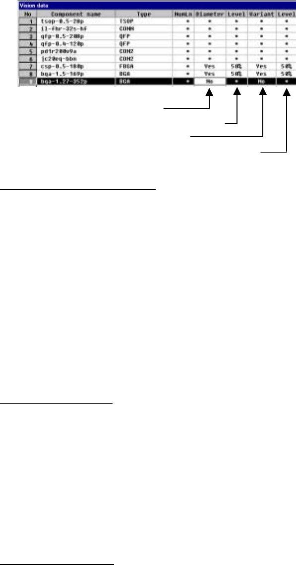
2) Settings for checking a ball
Set each ball shape check operation.
- Specify whether to check the diameter.
- Enter the level for checking the diameter (default: 50 %).
- Specify whether to check deformation of a ball.
- Enter the level for checking deformation of a ball (default: 50 %).
▼ Inspecting the diameter of a ball
The length and width of a ball is measured by the ball diameter inspection
function. If either of these measurements is not within the setting range, the
recognition error is supposed to occur. The diameter of a ball is inspected
based on the entered value, so enter the correct diameter of a ball. We
recommend that you specify 40 % or higher as the inspection level.
・ The entered value for the ball diameter is supposed to be R. If either of 1
- (H/R) or 1 - (V/R) is greater or smaller than the set value (%), the ball
diameter is regarded as "illegal".
▼ Inspecting the variation
This means the ball area inspection. The area of a ball is converted into
binary data, then its bright pixels are counted. The threshold of the binary data
is optimized for each ball. If the number of pixels counted is smaller or larger
than the value set for the ball area which is calculated from the entered
diameter value, the recognition error occurs. The ball area which is calculated
from the entered diameter value is converted into the number of pixels, then
inspected. Enter the correct ball diameter value in the same manner as that
for the ball diameter inspection. This function performs the stricter inspection
than the ball diameter inspection, so we recommend that you specify 45 % or
higher as the inspection level.
▼ Inspecting lack of a ball
If you specify “Inspect of diameter” or “Inspect of variation”, the system checks
whether any ball is omitted or not. This inspection is based on the average
value of each ball brightness and the total of each ball brightness to decide if a
ball should be omitted or not. A ball which is darker than other balls is handled
as nonexisting.
5 − 42
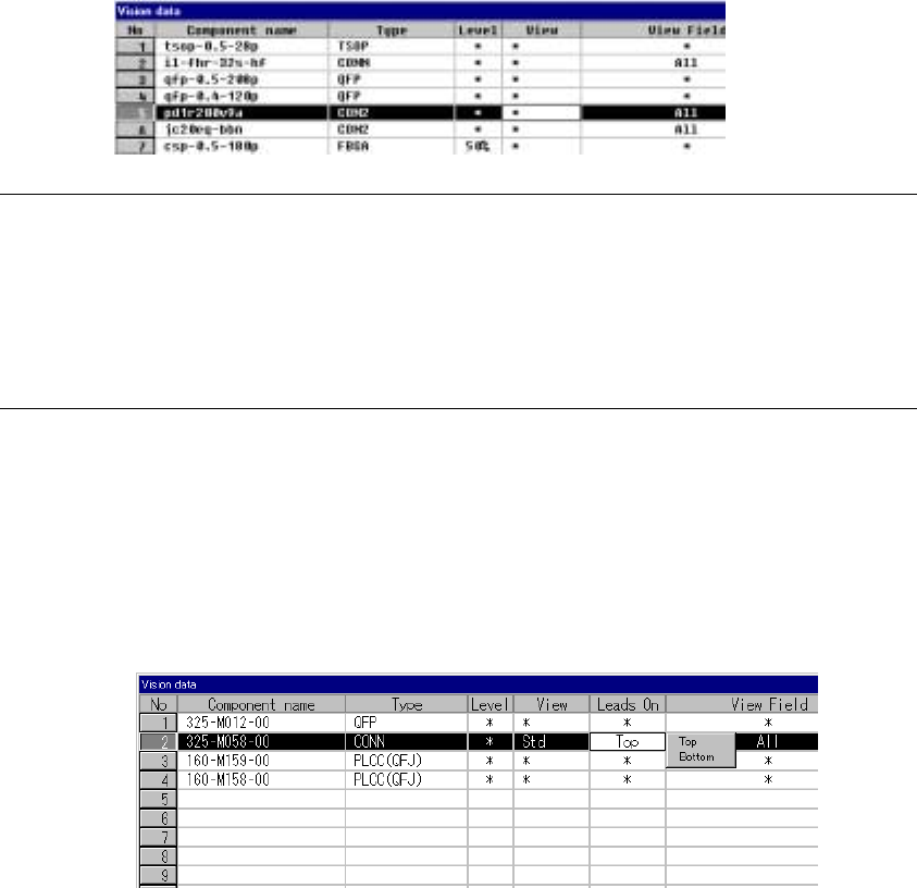
⑮ View
Set the field of view range when you want to recognize a component with
dividing its image.
- When you click this item with the right button, the selection pop-up menu
appears on the screen.
- You can select one of the settings: “Standard”, “Vertical 2”, and “Vertical
3”.
Notes:
①
This item is provided for compatibility with KE-740/760 data only. You cannot
set this item with any KE-2000 series of product.
For the field of view range, set the “Split Recognition” field of the “Vision
Control” dialog box.
②
Only the standard VCS can recognize a connector with dividing its image.
⑯ Lead direction
Set the lead direction.
Clicking the right button of the mouse displays the selection popup.
Select Up or Down as the lead direction.
5 − 43
Recognized
Recognized
Recognized
Recognized
Recognized
Recognized
The leads located at the inside are not recognized.
Recognized
Recognized
The leads located on the outside are not recognized.
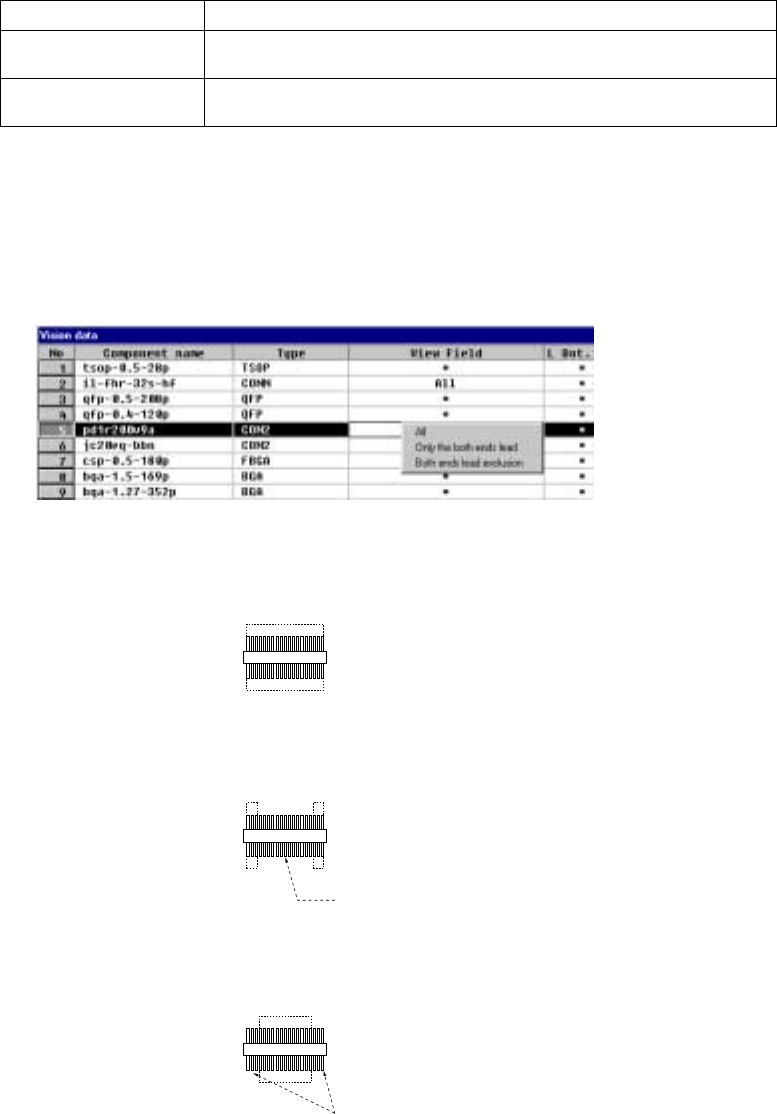
⑰ View Field, L Top, R Top, L Bot., and R Bot.
Set the range of leads to be recognized and that not recognized of a
connector.
When you click this setting item with the right button, the selection pop-up
menu appears on the screen.
All Recognizes all leads.
Only the both ends lead Specify the range of leads to be recognized with being viewed from the leads
on both ends.
Both ends lead exclusion Specify the range of leads not recognized with being viewed from the leads
on both ends.
- When you select “Only the both ends lead” or “Both ends lead exclusion”,
enter the number of leads on each side to the “L Top”, “R Top”, “L Bot.”, and
“R Bot.” fields to specify the range of leads recognized or not recognized.
- When you select “All”, you cannot specify the range of the number of leads.
1) Meaning and image of each lead recognition pattern
・ All leads: All leads are to be recognized.
・ Only the both ends lead:
Only leads located on both sides are to be recognized.
・ Both ends lead exclusion:
Leads except the specified leads located on both sides are to be
recognized.