KE2040Instruction Manual Ver2.01,REV04.2003.6.25.pdf - 第441页
5 − 51 Setting item Description Count Set the num ber of leads (balls) t o be check ed. Pitc h Set t he distanc e between two consecut ive leads (bal ls) to be check ed. Column, Row T olerance Enter the al lowable pitch …
5 − 50
3-2. Detailed description of each setting item
Setting item Description
Element group Name Enter up to 32 alphanumeric characters to assign an element group name. You
can omit this setting item. When omitted, “ELGxxxx” is assigned to an element
group, where xxxx is a four-digit integer automatically obtained.
Offset
(X, Y, Z, Theta)
Enter the coordinate of the center (or ball center for a ball component) of the
reference lead (reference element) end with being viewed from the center of a
component.
Note that when you select “2D” as the “Dimension”, enter “0” to the “Theta” field.
You cannot enter any other value here. The center of a component is normally
that of the outline of the component.
Tolerance Enter the allowable offset coordinate range.
First element
position
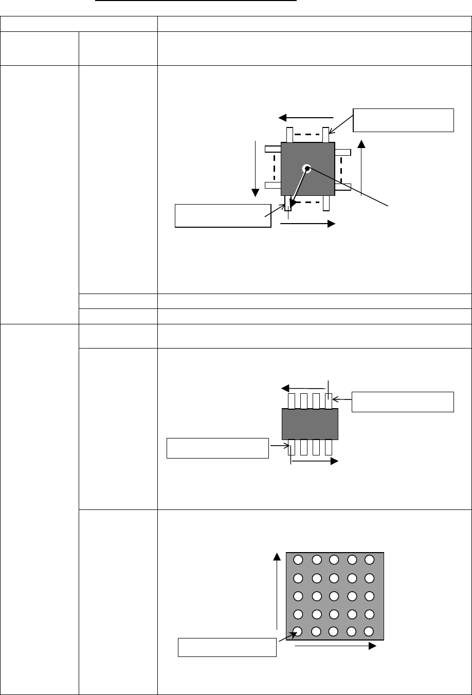
Layout inspection Set the level used for checking an element layout error (default: 20 %).
Point (Side,
corner, mark)
Select this radio button if you set only one lead (ball) to be checked.
1D (lead) Select this radio button if you set leads arranged in a column to be checked.
Dimension
2D (Ball, Land) Select this radio button if you set leads (balls) arranged in a row and column to be
checked.
Center of a
component
Reference element
Reference element
Arrangement direction (0 degrees)
(90°)
(270°)
(180°)
Arrangement direction
Reference element
Arrangement direction
TOPVIEW
Reference element
Reference element
Arrangement direction of
arow
BOTTOMVIEW
Arrangement direction of
a column
5 − 51
Setting item Description
Count Set the number of leads (balls) to be checked.
Pitch Set the distance between two consecutive leads (balls) to be
checked.
Column, Row
Tolerance Enter the allowable pitch range. (Not used)
Missing Elements Column,
Row
Start,
Count
Set the missing leads (balls) to be checked.
Up to four blocks of missing leads or balls can be set per
column/row.
Set blocks from a block of missing leads/balls nearest the
reference lead (ball).
Add Sets a new reference element.
Edit Allows you to edit an element already set.
Element
(Only one element can be set
for an element group.)
See Section 3-5 “Element”.
Delete Deletes an element.
OK Registers data then displays the “Extended Vision” screen,
where the registered data appears on the “Element Group
List”.
Cancel Cancels your entering/editing, then displays the “Extended
Vision” screen again.
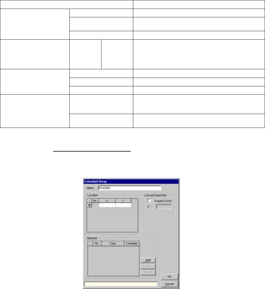
3.3 Extended array data format
When you check the “Extended array data format” check box, and click
the <Add> or <Edit> button, the following screen appears.
5 − 52
3-4 Detailed description of each setting item
Setting item Description
Name Enter a name (up to 32 alphanumeric characters) to be assigned to an extended
array.
You can omit this item. When omitted, “ENGxxxx” is assigned to a name, where
xxxx is a four-digit integer automatically obtained.
Location X, Y Enter the coordinates of a ball to be checked with being viewed from the center of
a component. Up to 256 balls can be defined.
Add Adds an element setting.
Edit Allows you to edit an element already set.
Element
See Section 3-5
“Element”.
Delete Deletes an element.
Layout inspection is performed by checking off the check box. Layout Inspection
Inspect Level Set the level used for checking a layout error.
OK Registers data then displays the “Extended Vision” screen where the registered
data appears on the “Extended Array List”.
Cancel Cancels your creating/editing, then displays the “Extended Vision” screen again.
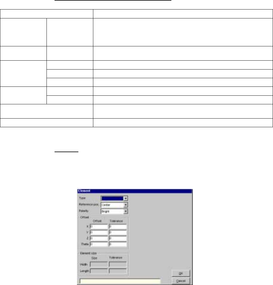
3.5 Element
When you click the <Add> or <Edit> button displayed on the “Element
Group” or “Extended Array” screen, the following screen appears.
- Set the conditions under which a lead (ball) is to be checked.
• When you select an element type from the “Type” combo box, the
following dialog box appears on the right side of the screen shown
above.