KE2040Instruction Manual Ver2.01,REV04.2003.6.25.pdf - 第56页
1 − 39 1.2.8 VCS parts identification The VCS recog nizes a component with the f ollowing devices: ref lective/penetra tive lights, three- dimension movable light and coaxial light, t hen places on a board a component su…
1 − 38
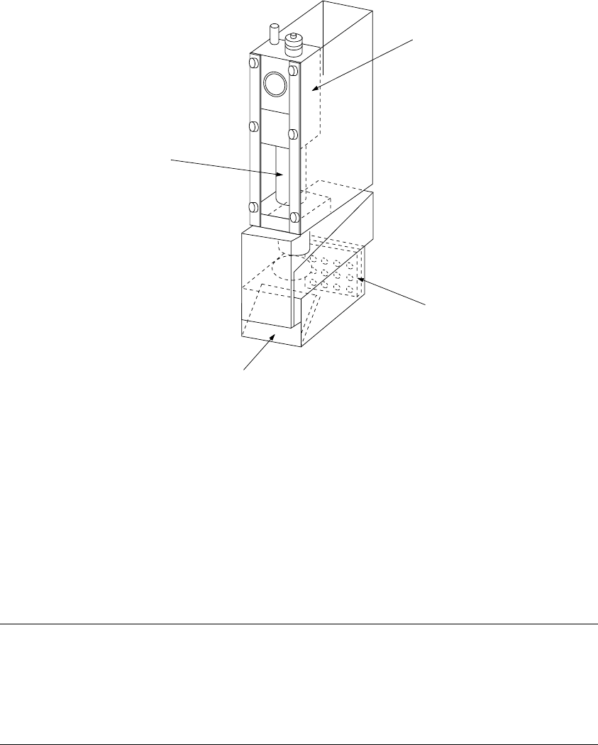
1.2.7 OCC parts identification
(1) Offset correction camera
The machine is equipped with a coaxial light and polarizing filter as the standard
devices. The camera detects a BOC mark and corrects the detected mark
automatically.
① OCC camera
② OCC lens
③ Illumination LED board
④ Mirror box
Figure 1.2.7.1
Adjusting the polarizing filter
1) Place a white ceramic board on the calibration block, then move the camera over
this board.
2) Loosen the screw to turn the filter holder to the right and left. When the screen
becomes brightest, fix the screw.
①
④
③
1 − 39
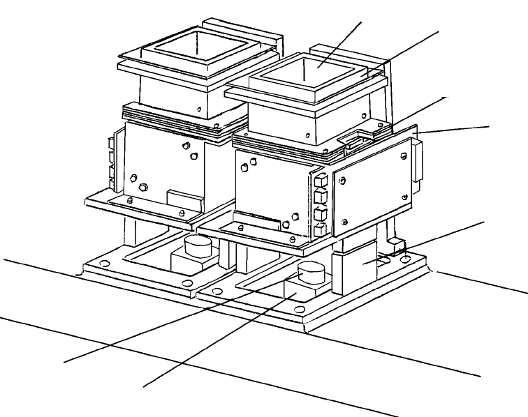
1.2.8 VCS parts identification
The VCS recognizes a component with the following devices: reflective/penetrative
lights, three-dimension movable light and coaxial light, then places on a board a
component such as a QFP, BGA, CSP and connector.
Figure 12.8.1 VCS unit parts identification
① LED board (for the penetrative light)
② LED board (for the side light)
③ LED board (for the bottom light)
④ LED board (for the coaxial light)
⑤ VCS lens
⑥ VCS camera
⑦ Air cylinder
①
②
③
④
⑦
⑥
⑤
1 − 40
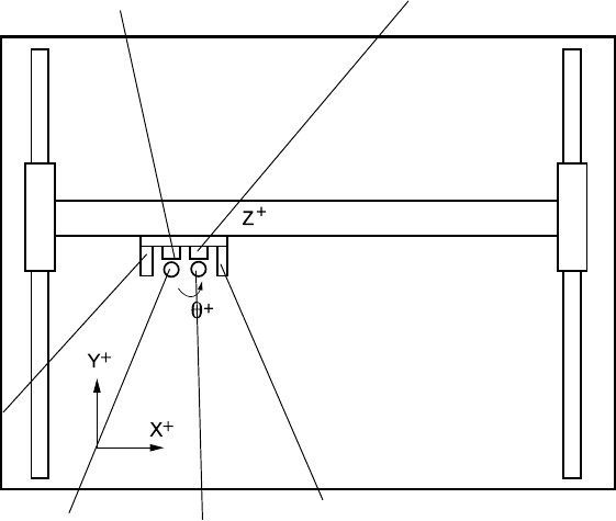
1.3 X, Y, and Z Axes Descriptions
The following four axes (X, Y, Z, and θ) are numerically controlled in this machine.
(1) X- and Y-axis
The X-axis represents the left and right directions of the machine, while the
Y-axis represents the front and rear directions: a position is given as X = 000.00
mm and Y = 000.00 mm in increments of 0.01 mm. Two coordinate systems are
available: one given by the production program and another given by teaching
operation. Both coordinate systems are automatically changed, so you do not
have to switch the coordinate system by yourself.
(2) Z-axis
The Z-axis represents the height, given as Z = ○○.○○ mm, in 0.01-mm
increments. The upward direction is positive (+), with the top side of a board
clamped (any jig is not used) being 0.
(3) θ-axis
The q-axis represents the rotation angle of the head, given as "A = ○○.○○" (in
0.05 increments.) The value is positive for counterclockwise rotation and
negative for clockwise rotation.
Figure 1.3.1
FMLA head unit (L)
Y axis
OCC-L
FMLA head unit (R)
OCC-R
IC nozzle axis
IC nozzle axis
X axis