00197975-06_UM_TX-Serie_EN.pdf - 第123页
User manual SIPLACE TX-Series 3 Technical data and assemblies From software version 713.0 Edition 01/2020 3.5 Placement head 123 3.5.1.3 T echnical data for SIPLACE S peedSt ar (C&P20 M2) on SIPLA CE TX micron 3 SIPL…
3 Technical data and assemblies User manual SIPLACE TX-Series
3.5 Placement head From software version 713.0 Edition 01/2020
122
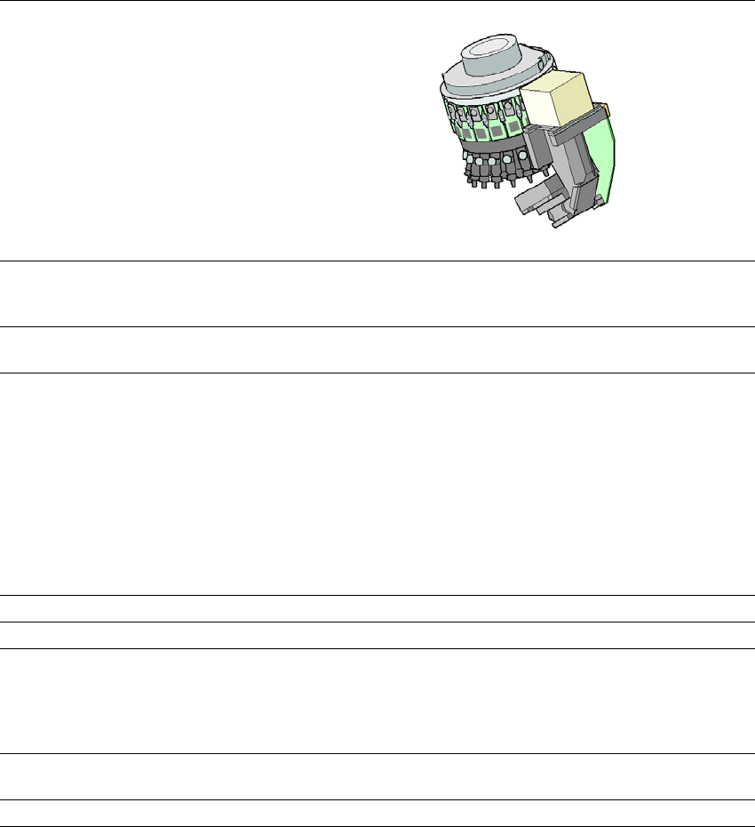
3.5.1.2 Technical data SIPLACE SpeedStar (C&P20 P)
3
SIPLACE SpeedStar (C&P20 P)
With component camera
type 23
With component camera type 41
Component range
*a
*)a Please note that the placeable component range is also affected by the pad geometry, the customer-spe-
cific standards, the component packaging tolerances and the component tolerances.
01005 to 2220, Melf, SOT,
SOD
0201 (metric) to 2220, Melf, SOT, SOD,
Bare-Die, Flip-Chip
Component spec.
Max. height
Min. lead pitch
Min. lead width
Min. ball pitch
Min. ball diameter
Min. dimensions
Max. dimensions
Max. weight
4 mm
250 µm
100 µm
400 µm
200 µm
0.18 mm x 0.18 mm
6mm x 6 mm
1 g
4 mm
80 µm
30 µm
100 µm
50 µm
0.12 mm x 0.12 mm
6 mm x 6 mm
1 g
Set-down force Touchless Placement, 0.5 N, 1 N to 4.5 N
Nozzle types 40xx 40xx
X/Y accuracy
*b
*)b The accuracy values fulfill the conditions in the ASM scope of supply and services.
± 30µm / 3σ ± 30 µm/3σ
± 25 µm/3σ
*c
*)c With accuracy class. Setting in SIPLACE Pro Component Shape Editor.
Angular accuracy ± 0.5° / 3σ ± 0.5° / 3σ
Illumination level 5 5
Standard functions Vacuum sensor, force measurement, PCB warpage check,
individual image of each component
Options Nozzle changer, special nozzles
User manual SIPLACE TX-Series 3 Technical data and assemblies
From software version 713.0 Edition 01/2020 3.5 Placement head
123
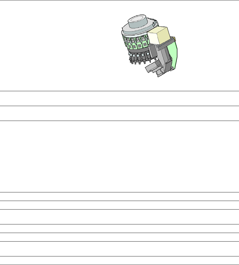
3.5.1.3 Technical data for SIPLACE SpeedStar (C&P20 M2) on SIPLACE TX micron
3
SIPLACE SpeedStar (C&P20 M2)
With component camera type
48
(Standard)
With component
camera type 49
(Optional)
Component range
*a
*)a Please note that the placeable component range is also affected by the pad geometry, the customer-specific
standards, the component packaging tolerances and the component tolerances.
0.12 mm x 0.12 (0201 metric) to 2220, Melf, SOT, SOD, Bare-
Die, Flip-Chip
Component spec.
Max. height
Min. lead pitch
Min. lead width
Min. ball pitch
Min. ball diameter
Min. dimensions
Max. dimensions
Max. weight
4 mm
70 µm
30 µm
100 µm
50 µm
120 µm x 120 µm
6 mm x 6 mm
1 g
4 mm
*b
50 µm
25 µm
50 µm
25 µm
80 µm x 80 µm
6 mm x 6 mm
1 g
*)b Due to the small area of focus of ±0.3 mm, this camera is only recommended if this particular camera res-
olution is required for the components. The nozzle length needs to be adjusted in accordance with the area
of focus and component thickness. The maximum component size for use remains 6 mm x 6 mm.
Set-down force Touchless Placement, 0.5 N, 1 N to 4.5 N
Nozzle types 40xx 40xx
X/Y accuracy
*c
With "accuracy class"
*d
Without "accuracy class"
*)c The accuracy values fulfill the conditions in the ASM scope of supply and services.
*)d Setting in SIPLACE Pro Component Shape Editor.
± 15 µm/3σ
*e
± 20 µm/3σ
± 20 µm/3σ
*)e Only with SIPLACE TX2i micron 15µm accuracy class
± 15 µm / 3σ
e
± 20 µm/3σ
± 20 µm/3σ
Angular accuracy ± 0.3° / 3σ
*f
± 0.2° / 3σ
*g
*)f For SIPLACE TX micron with accuracy class 25 µm
*)g For SIPLACE TX micron with accuracy class 20 µm or SIPLACE TX2i micron 15µm
± 0.3° / 3σ f
± 0.2° / 3σ
g
Illumination level 5 5
3 Technical data and assemblies User manual SIPLACE TX-Series
3.5 Placement head From software version 713.0 Edition 01/2020
124
3.5.2 Sensor for the component reject bin
The sensor for the component reject bin monitors whether the reject bin is seated correctly in its
mount.
– If the reject bin was not inserted correctly, the placement machine cannot be started.
– If the reject bin jumps out of its mount during the placement process, the placement machine
will be stopped immediately to avoid a head crash.
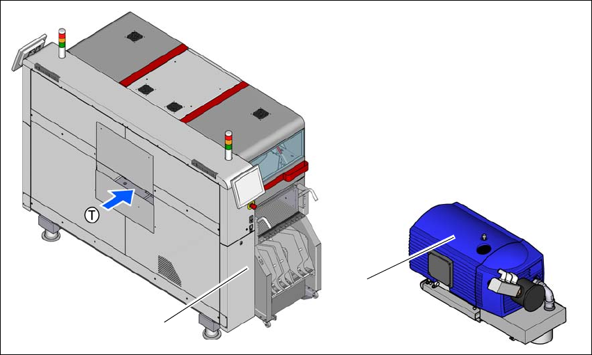
3.5.3 Vacuum pump (optional)
The vacuum pump for the SIPLACE SpeedStar is fitted behind the cover at location 1, in the ma-
chine frame.There are two types available:
– Vacuum pump VX4.25
– Vacuum pump VX4.25/0-47 IE3
3.5.3.1 Overview - type VX4.25
Item no. 03128463-xx Vacuum pump VX4.25
3
Fig. 3.5 - 2 Overview - vacuum pump
(1) Installation location for vacuum pump
(2) Vacuum pump VX 4.25
(2)
(1)