00197975-06_UM_TX-Serie_EN.pdf - 第87页
User manual SIPLACE TX-Series 2 Operational safety From software version 713.0 Edition 01/2020 2.5 Safety features 87 Position switch location 1 and 2 (item 1 and 4 in fig. 2.5 - 4 , page 84 ) 2 This position switch chec…

2 Operational safety User manual SIPLACE TX-Series
2.5 Safety features From software version 713.0 Edition 01/2020
86
Start button (item 1 in fig. 2.5 - 2, page 82 and item 1 in fig. 2.5 - 3, page 83) 2
After switching on the main switch you will be prompted to press the start button in order to start
the placement machine for placement jobs. The same prompt appears if you open the protective
covers or the press the EMERGENCY STOP button.
Press the start button for at least 200 ms, up to a maximum of 1500 ms, and then let go. The
placement machine will be switched on when you let go of the button and the protective cov-
ers will be mechanically held closed.
Stop button, black (item 2 in fig. 2.5 - 2, page 82 and item 2 in fig. 2.5 - 3, page 83) 2
These buttons are used to stop the placement machine. The mechanical closure on the protective
cover lock is released and the covers can be opened.
Component counter 2
The number of placed components (component counter) can be read on the station software. For
more information, refer to the Online Help.
EMERGENCY STOP button with forced locking (item 3 in fig. 2.5 - 2, page 82 and item 3 in fig.
2.5 - 3, page 83) 2
The EMERGENCY STOP button is red and latches in the ON position when pressed. When you
press the EMERGENCY STOP button, the switching contact of the EMERGENCY STOP circuit
opens and the safety cutoff (CBS) trips. The intermediate circuit voltage (300 VDC) for the gantry
axes and the intermediate circuit voltage (160 VDC) for the star axes is switched off. The servo
amplifiers for the DP and Z axes are still supplied with 42 VDC. The signaling contact of the
EMERGENCY STOP button opens and the message "EMERGENCY STOP pressed" appears on
the screen. The following modules are deactivated:
– PCB conveyor
– PCB clamping
– Width adjustment
– PCB stopper
– Feeder Control Unit
– Compressed air supply for empty tape cutter
2
PLEASE NOTE
Placement will be interrupted and can then either be continued or canceled, once the
placement machine is working correctly again.

User manual SIPLACE TX-Series 2 Operational safety
From software version 713.0 Edition 01/2020 2.5 Safety features
87
Position switch location 1 and 2 (item 1 and 4 in fig. 2.5 - 4, page 84) 2
This position switch checks whether the protective covers are open or closed. The position
switches on the protective covers trigger the safety cutoff (lock) when a protective cover is
opened. Individual components are disabled or remain enabled (see fig. 2.5 - 6
, page 91 ). The
protective covers are mechanically locked during placement machine operation. The protective
covers can only be opened once the stop button has been pressed.
Protective cover switch for COT insert location 1 and 2 (item 2 and 3 in fig. 2.5 - 4, page 84) 2
This switch checks whether the component trolley is docked onto the COT insert. When they are
closed, the EMERGENCY STOP contact and the signaling contact are closed. If one of the com-
ponent trolleys is docked on, the EMERGENCY STOP contact and the signaling contact will open.
2 Operational safety User manual SIPLACE TX-Series
2.5 Safety features From software version 713.0 Edition 01/2020
88
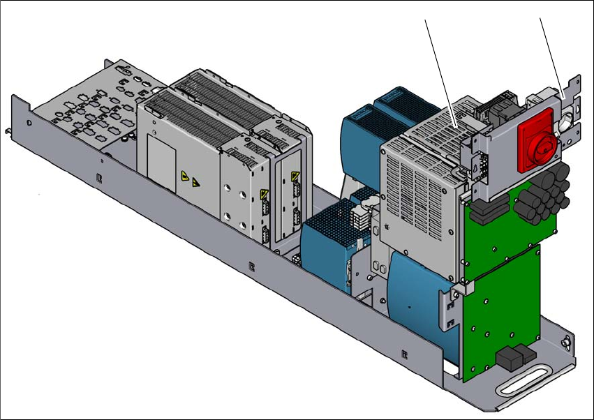
2.5.3 Safety cutoff (CSB)
2
Fig. 2.5 - 5 Position of the safety cutoff (CSB)
2
(1) Safety cutoff (CSB)
(2) Service socket (if present)
(1)
(2)