00197975-06_UM_TX-Serie_EN.pdf - 第208页
4 Setting up and commissioning Us er manual SIPLACE TX-Series 4.5 Setting up the placement mac hine From software version 713.0 Edition 01/2020 208 4.5.6 Setting the conveyor height and aligning the placement mac hine 4.…

User manual SIPLACE TX-Series 4 Setting up and commissioning
From software version 713.0 Edition 01/2020 4.5 Setting up the placement machine
207
4.5.5.3 Pallet truck specification for lifting at the locations
The pallet truck must compensate the uneven weighting on its forks and guarantee a horizontal
position when loaded.
If you lift the placement machine at the locations, you will need to use a pallet truck with the fol-
lowing specifications:
4
4
Fork length Min. 1800 mm
Lifting power Min. 3000 kg

4 Setting up and commissioning User manual SIPLACE TX-Series
4.5 Setting up the placement machine From software version 713.0 Edition 01/2020
208
4.5.6 Setting the conveyor height and aligning the placement machine
4.5.6.1 PCB conveyor height on the placement machine
The placement machine can be set to the following PCB conveyor heights:
900 mm ± 15 mm 4
930 mm ± 15 mm (standard height) 4
950 mm ± 15 mm (SMEMA height) 4
4
4.5.6.2 Tools and equipment
You will need the following tools and equipment to adjust and set the height of your placement
machine:
– Torque wrench 100 Nm to 400 Nm, item no. 03122973-01
– Tool holder for reversible ratchet 800mm, item no. 03122976-01
– Attachable ratchet 34 inch 14x18, item no. 03122977-01
– Extension 1/2 inch, item no. 03080499-01
– 03122975-01 Inbus bit SW19x85mm 34 inch, item no. 03122975-01
– 03122979-01 UVEX bump cap SHORT. Item no. 03122979-01
– Hexagonal screwdriver bit, size 14
– Open-end wrench 18 mm
– Shaft spirit level (accuracy 0.02 mm/m), item no. 00353825-01
– Pallet truck (specifications see 4.5.5.3 on page 207).
– Air cushion transport system: SIPLACE HSxx, Item No. 00119002-S01 (optional)
PLEASE NOTE
The PCB conveyor height is the distance between the top edge of the PCB conveyor belt
and the bottom edge of the machine feet.
User manual SIPLACE TX-Series 4 Setting up and commissioning
From software version 713.0 Edition 01/2020 4.5 Setting up the placement machine
209
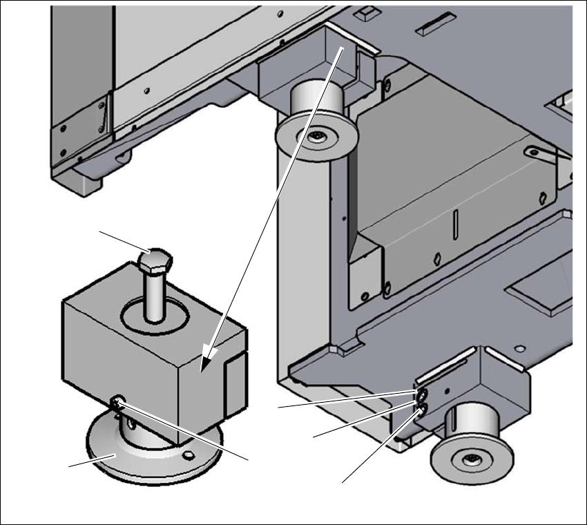
4.5.7 Setting the conveyor height
The placement machine stands on four machine feet.
4
Fig. 4.5 - 5 Setting the PCB conveyor height
(1) Setting screw for height adjustment
(2) Machine foot
(3) Locking screws for machine foot
(4) Two clamping screws
(5) Threaded hole between the two clamping screws (to spread open the clamp)
Loosen the locking screw (3). The locking screw prevents falling down right after the clamp
has been loosened.
Loosen the two clamping screws (4), using the attachable ratchet and the hexagonal screw-
driver bit, size 14.
(1)
(4)
(3)
(2)
(5)
(4)