00197975-06_UM_TX-Serie_EN.pdf - 第139页
User manual SIPLACE TX-Series 3 Technical data and assemblies From software version 713.0 Edition 01/2020 3.5 Placement head 139 3.5.5.1 Description This sophisticated placement hea d consists of two placement hea ds of …
3 Technical data and assemblies User manual SIPLACE TX-Series
3.5 Placement head From software version 713.0 Edition 01/2020
138
3.5.5 SIPLACE TwinStar for high precision IC placement
3
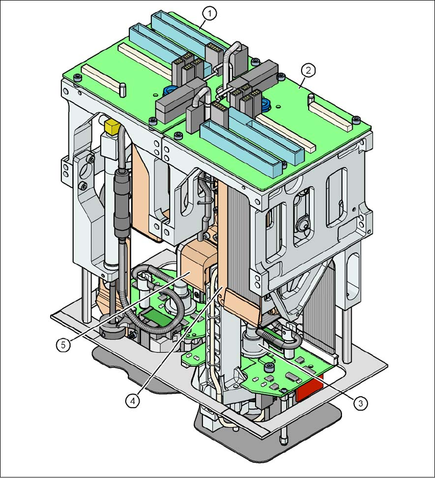
Fig. 3.5 - 10 SIPLACE TwinStar for high precision IC placement
3
(1) Pick&Place module 1 (P&P1) - the TwinStar consists of 2 Pick&Place modules
(2) Pick&Place module 2 (P&P2)
(3) DP axis
(4) Z axis drive
(5) Incremental distance measuring system for the Z axis
User manual SIPLACE TX-Series 3 Technical data and assemblies
From software version 713.0 Edition 01/2020 3.5 Placement head
139
3.5.5.1 Description
This sophisticated placement head consists of two placement heads of the same type coupled to-
gether. Both heads work using the Pick&Place principle. The TwinStar is suitable for processing
complex and large components. Two components are picked up by the placement head, optically
centered on the way to the placement position and rotated into the necessary placement angle.
They are then placed gently and accurately onto the PCB with a controlled blast of air.
New nozzles (type 5xx) have been developed for the TwinStar. With an adapter you can also use
the nozzles of type 4xx from the Pick&Place head and nozzles of type 8xx, 9xx and 2xx from the
Collect&Place heads.
3 Technical data and assemblies User manual SIPLACE TX-Series
3.5 Placement head From software version 713.0 Edition 01/2020
140
3.5.5.2 Technical data Twin Star
SIPLACE TwinStar
with component camera type 33
(fine pitch camera)
with component camera type 25
(flip chip camera)
Component range
*a
0402 to SO, PLCC, QFP, BGA, special
components, bare dies, flip-chips
0201 to SO, PLCC, QFP, sockets, plugs,
BGA, special components, bare dies, flip-
chips, shields
Component specs
*b
Max. height
Min. lead pitch
Min. lead width
Min. ball pitch
Min. ball diameter
Min. dimensions
Max. dimensions
Max. weight
*c
25 mm (higher available on request)
300 µm
150 µm
350 µm
200 µm
1.0 mm x 0.5 mm
55 mm x 45 mm (single measurement)
Up to
200 mm x 125 mm (multiple measurement)
*d
160 g
*e
25 mm (higher available on request)
250 µm
100 µm
140 µm
80 µm
0.6 mm x 0.3 mm
16 mm x 16 mm (single measurement)
160 g*
e
Set-down force 1.0 N - 15 N
2.0 N - 30 N with OSC package
1.0 N - 15 N
2.0 N - 30 N with OSC package
Nozzle types
*f
5xx (standard)
20xx/28xx + adapter
4xx + adapter
9xx + adapter
gripper
5xx (standard)
20xx/28xx + adapter
4xx + adapter
9xx + adapter
gripper
Nozzle spacing for P&P
heads
70.8 mm 70.8 mm
X/Y accuracy
*g
± 28 µm/3σ ± 22 µm/3σ
Angular accuracy ± 0.05° / 3σ, ± 0.05° / 3σ
Illumination level 6 6
*)a Please note that the placeable component range is also affected by the pad geometry, the customer-specific standards, the
component packaging tolerances and the component tolerances.
*)b If the MultiStar and TwinStar are combined in the same placement area, the maximum component height may be restricted.
*)c If standard nozzles are used
*)d Depending on the component dimensions and component infeed, other restrictions may also apply, which SIPLACE Pro will
automatically take into account.
*)e Up to 100 g is standard. Over 100 g available with reduced acceleration.
*)f Over 300 different nozzles and 100 gripper types are available, with an extensive nozzle database available online.
*)g The accuracy values fulfill the conditions in the SIPLACE scope of supply and services.