00197975-06_UM_TX-Serie_EN.pdf - 第52页
2 Operational safety User manual SIPLACE TX-Series 2.2 Warning labels From software version 713.0 Edition 01/2020 52 2.2.3.4 W arning label W 012 2 W 01 2 in fig. 2.2 - 1 , page 45 , 2.2 - 2 , p age 46, and fig. 2.2 - 2 …
User manual SIPLACE TX-Series 2 Operational safety
From software version 713.0 Edition 01/2020 2.2 Warning labels
51
2.2.3 Meaning and description of warning labels
2.2.3.1 Information sign M002
2
MW 002 in fig. 2.2 - 1, page 45, item no. 03155798-01 or
MW 002 in fig. 2.2 - 4
, page 48, item no. 03155798-01
(Quantity per placement machine: 1)
2.2.3.2 Warning label laser class 2
2
W Laser class 2 in fig. 2.2 - 1, page 45, item no. 03134118-01 (quantity per placement machine: 1)
2.2.3.3 Warning label W 024
2
W 024 in fig. 2.2 - 1, page 45, 2.2 - 2, page 46 and 2.2 - 2, page 46 item no. 03155346-01
(Quantity per placement machine: 8)
2
2
2
2
2
2
2
2
Safe operation of placement machine
Safe operation of the placement machine depends absolutely on
the operator being familiar with the instruction manual and safety
instructions and putting them into effect.
2
LASER RADIATION
Laser class 2
Acc. to IEC 60825-1:2014
Do not look into beam!
2
2
2
Warning about hand injuries
Reaching in here can lead to injuries to the arms and hands.
Do not reach into the running placement machine.
Do not reach into the inside of the adjacent placement ma-
chine
2 Operational safety User manual SIPLACE TX-Series
2.2 Warning labels From software version 713.0 Edition 01/2020
52
2.2.3.4 Warning label W 012
2
W 012 in fig. 2.2 - 1, page 45, 2.2 - 2, page 46, and fig. 2.2 - 2, page 46, item no. 03155378-01 or
W 012 in fig. 2.2 - 4
, page 48, 2.2 - 5, page 49, and fig. 2.2 - 6, page 50, item no. 03155378-01
(Quantity per placement machine: 5)
2.2.3.5 Warning label W 210
2
W 210 in fig. 2.2 - 1, page 45 and 2.2 - 2, page 46, item no. 03009350-01 (quantity per placement
machine: 2)
2.2.3.6 Warning label W 209
2
W 209 in fig. 2.2 - 1, page 45 and 2.2 - 2, page 46, item no. 03009349-01
(Quantity per placement machine: 2)
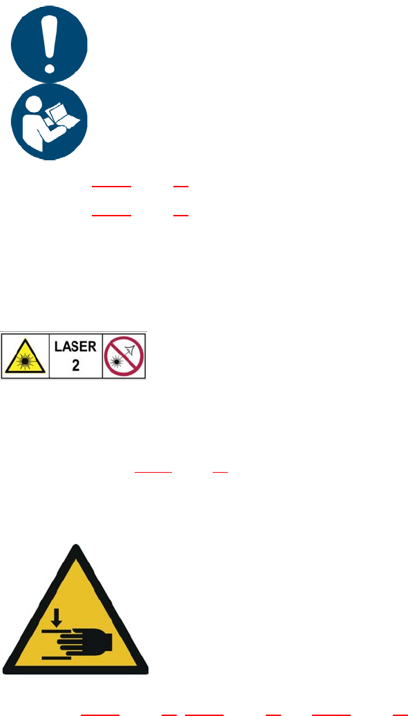
Dangerous voltages
Marked parts are initially still live when the main power switch is off
and the mains plug has been disconnected.
Disconnect the placement machine from the mains before opening
the cover.
NAFTA region: RISK OF ELECTRIC SHOCK OR BURN!
2
2
2
2
2
2
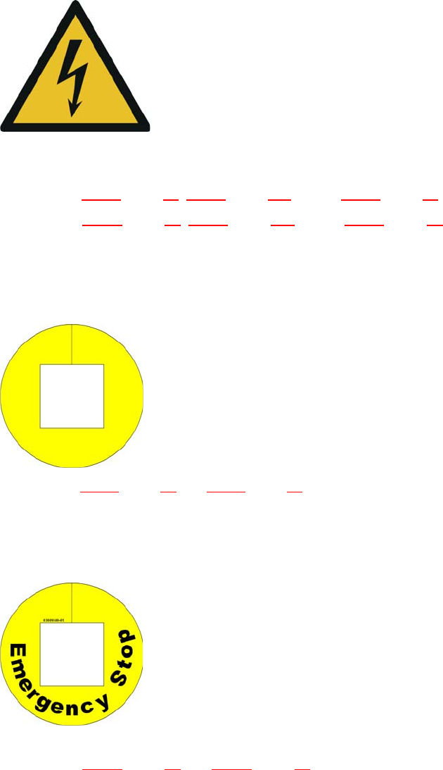
Warning label on the EMERGENCY STOP button
2
2
2
2
2
2
2
2
2
2
For Australia, Canada, Mexico and USA, warning label
W209 is affixed to the extension kit instead of the yellow
ring on the EMERGENCY STOP buttons.
User manual SIPLACE TX-Series 2 Operational safety
From software version 713.0 Edition 01/2020 2.2 Warning labels
53
2.2.3.7 Warning strips on the inside of the output conveyor
2
A black-yellow warning strip is attached to the inside, above the output conveyors. Item 2 in the
fig. 2.2 - 4
, page 48 (quantity per placement machine: 1)
This warns the operator not to reach into the inside of the neighboring machine.
2
2.2.3.8 NO attachment points for transportation with fork-lift
Item P 006 in fig. 2.2 - 2, page 46 and 2.2 - 4, page 2.2 - 4, item no. 03155631-xx or
Item P 006 in fig. 2.2 - 5
, page 49 and 2.2 - 6, page 50, item no. 03155631-xx
(Quantity per placement machine: 4)
DANGER
Risk of injury when protective cover open!
There is a risk of injuries if you reach into the hazard area of the adjacent machine when
the protective cover is open. This area is marked with black-and-yellow warning strips.
Take care not to reach into the hazard area of the adjacent machine when the pro-
tective cover is open.
2
2
2
Risk of hand injuries (crushing) over an extensive area
Reaching in here can lead to injuries to the arms and hands.
Do not reach into the inside of the neighboring machine.
2
2
2
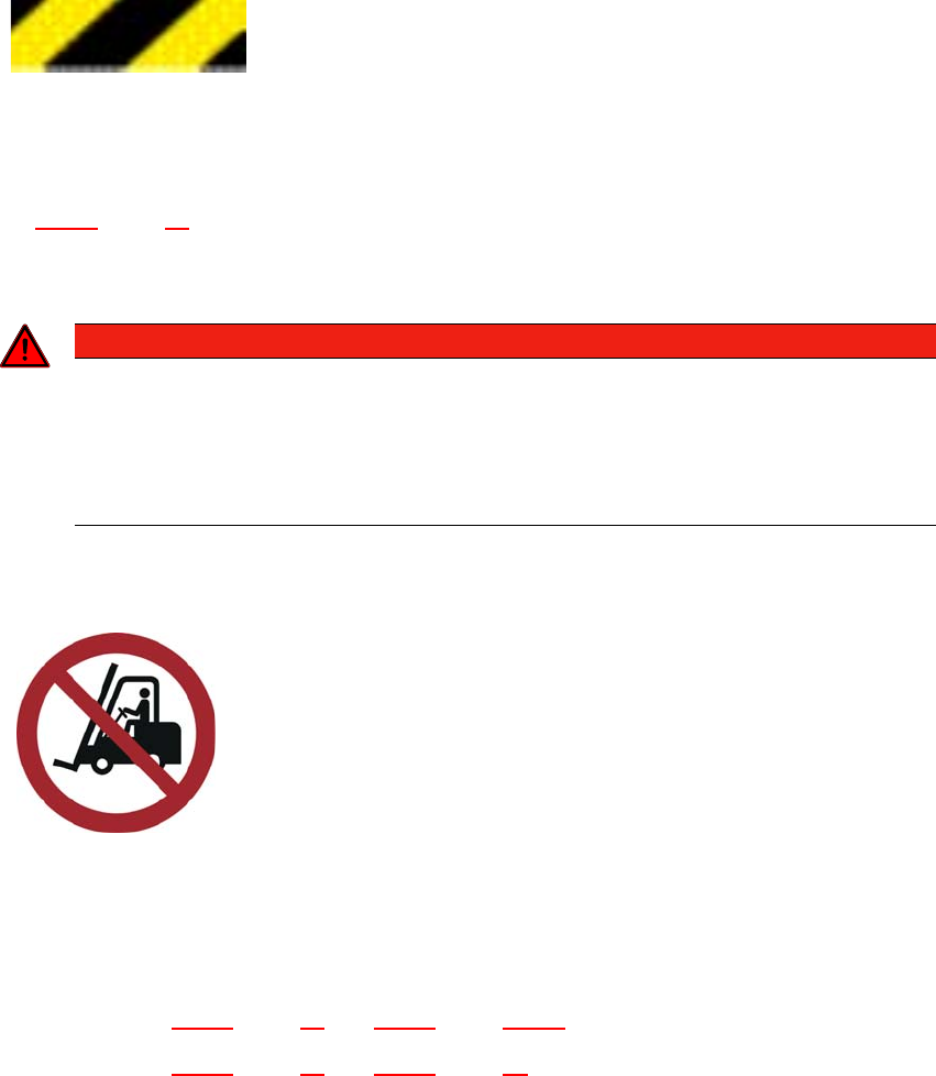
NO attachment points for transportation with fork-lift
Transportation of the placement machine with a fork-lift is prohib-
ited at these marked points. The placement machine could tilt
over. This poses a risk of severe injury and damage to property.
The placement machine may ONLY be lifted and transported
with the fork-lift at the output side of the placement machine.
Read and observe the chapter "Setting up and commis-
sioning" on page 175.