00197975-06_UM_TX-Serie_EN.pdf - 第256页
5 Tasks at the placement machi ne User manual SIPLACE TX-Series 5.10 Setting up the feeder modules From software version 713.0 Ed ition 01/2020 256 5.10 Setting up the feeder modules 5.10.1 Notes on handling feeder modul…

User manual SIPLACE TX-Series 5 Tasks at the placement machine
From software version 713.0 Edition 01/2020 5.9 Carrying out a sight check
255
5.9.3 Checking the PCB supports
Check the position of the magnetic PCB supports on the lifting table:
– Make sure that the PCB supports do not collide with components on the underside of the
PCBs.
– In addition, make sure that the PCB supports do not collide with the PCB conveyor pan-
els.
– Only use PCB supports as described in section 6.9
, page 313.
5 Tasks at the placement machine User manual SIPLACE TX-Series
5.10 Setting up the feeder modules From software version 713.0 Edition 01/2020
256
5.10 Setting up the feeder modules
5.10.1 Notes on handling feeder modules
Feeder modules are precision devices. You should therefore handle the feeder modules with care.
Avoid bumping feeder modules into obstacles.
Do not drop the feeder modules.
Always use suitable tools for preventive maintenance.
5.10.2 Removing X feeder modules from the changeover table
5
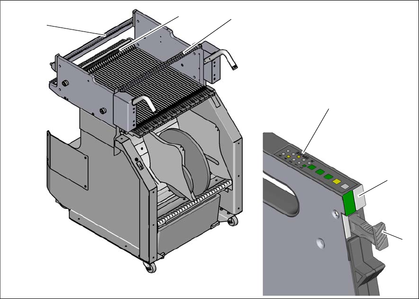
Fig. 5.10 - 1 Removing X feeder modules from the changeover table
(1) Removal handle
(2) Status display
(3) LED display
(4) Rail for checking height of feeder
(5) Latch for locking the feeder modules
(6) Centering rail
5
(2)
(1)
(4)
(5)
(6)
(3)

User manual SIPLACE TX-Series 5 Tasks at the placement machine
From software version 713.0 Edition 01/2020 5.10 Setting up the feeder modules
257
On standby, the status display (item 2 in fig. 5.10 - 1, page 256) lights up green if the X axis feeder
module is contained in the current setup. If the feeder module is not contained in the current setup,
the status display remains off.
The feeder module is locked in position in the changeover table by a latch, and cannot be pulled
out. The procedure for removing feeder modules from the changeover table is as follows:
Press the removal handle (item 1 in fig. 5.10 - 1, page 256). The removal handle jumps out
and the status display goes out.
Wait approximately 1 second until the lock (item 4 in fig. 5.10 - 1, page 256) releases the
feeder module.
Use the removal handle to pull the feeder module out of the changeover table. If you wait lon-
ger than 5 seconds, the feeder module will be locked once more. The status display will shine
red.
Engage the removal handle once more. If the feeder module is contained in the current setup,
the status display lights up green and the track number and increment will appear on the LCD
display once more.