00197975-06_UM_TX-Serie_EN.pdf - 第213页
User manual SIPLACE TX-Series 4 Setting up and commissioning From software version 713.0 Edition 01/2020 4.5 Setting up the pl acement machine 213 4 Fig. 4.5 - 7 Contact positions fo r the air cushion transport system (1…

4 Setting up and commissioning User manual SIPLACE TX-Series
4.5 Setting up the placement machine From software version 713.0 Edition 01/2020
212
4.5.7.2 Aligning and adjusting the placement machines in the line
Use the pallet truck to move the placement machine to its rough position and then lower the
placement machine into position. While doing this, observe the safety instructions and proce-
dural instructions in section 4.5.5.1
, page 205.
Align the placement machine vertically (height) and horizontally with the help of the machine
spirit level.
Position the placement machine so that there is a smooth transition between the PCB con-
veyors for the adjacent placement machine.
Check the height and horizontal position and correct, if necessary.
Check the transition between the PCB conveyors and correct, if necessary.
If both are OK, use the torque wrench to tighten the clamping screws (torque of 130 Nm) for
the four machine feet. (See also diagram 4.5 - 5
, page 209)
4.5.7.3 Aligning the placement machine with the air cushion transport system
Place the four air cushions from the air cushion transport system under the contact points
(see fig. 4.5 - 7
, page 213).
4
Raise the placement machine and align it with respect to the line.
Check the distance from the PCB conveyor system of the adjacent placement machine. It
should be between 1 mm and 3 mm.
Lower the placement machine.
WARNING
Avoid swinging up of the placement machine - observe the instruction manual for the air
cushion transportation system!
Observe the handling and safety instructions in the user manual for the air cushion
transport system.
Regulate the supply of air very carefully, to prevent the placement machine from
swinging up.
User manual SIPLACE TX-Series 4 Setting up and commissioning
From software version 713.0 Edition 01/2020 4.5 Setting up the placement machine
213
4
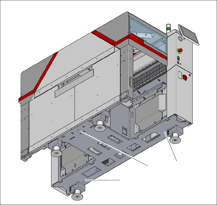
Fig. 4.5 - 7 Contact positions for the air cushion transport system
(1) Three contact points for the air cushion transport system
(1)
(1)
(1)
4 Setting up and commissioning User manual SIPLACE TX-Series
4.5 Setting up the placement machine From software version 713.0 Edition 01/2020
214
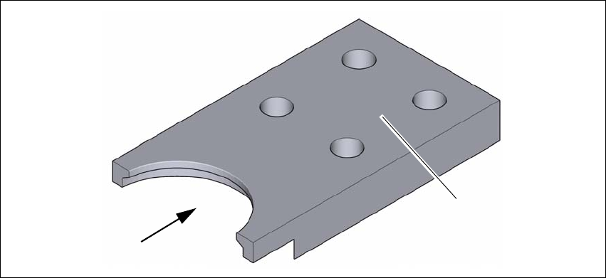
4.5.7.4 Fitting the floor brace (optional)
Item no. 00588122-xx Floor brace set for TX
The placement machine can be secured against sliding in the event of strong vibrations (e.g.
earthquakes) with a floor brace, if required.
Fit a floor brace to each placement machine foot.
4
Fig. 4.5 - 8 Floor brace
Place the floor brace (1) over the placement machine foot.
Attach the floor brace to the ground with suitable fixtures, at the four holes (2) provided.
(1)
(2)