00197975-06_UM_TX-Serie_EN.pdf - 第91页
User manual SIPLACE TX-Series 2 Operational safety From software version 713.0 Edition 01/2020 2.5 Safety features 91 2 Fig. 2.5 - 6 EMERGENCY STOP loops S tart button pressed. No No Ye s No No Ye s Ye s 2 Active Safety …
2 Operational safety User manual SIPLACE TX-Series
2.5 Safety features From software version 713.0 Edition 01/2020
90
2.5.3.1 Overview of safety cutoff
When the placement machine is ready for operation, the contacts of all position switches and the
EMERGENCY STOP buttons are closed. If a protective cover, for example, is raised, the corre-
sponding switch and safety cutoff will be triggered. For the operator's information, this status
change is signaled to the control computer via a digital CAN bus input signal from the I/O control
unit. An error message to this effect appears on the user interface.
Prerequisites 2
The following conditions must be fulfilled in order to start and operate the placement machine:
– All component trolleys must be docked into place.
– All protective covers on the placement machine must be closed.
– The two emergency STOP buttons must be released.
– The minimum operating pressure must have been reached.
– The software release ("Control ON") must be enabled.
If one of the start buttons is now pressed, the safety cutoff (CBS) will switch the safety-controlled
supply voltages on and the placement machine will be ready for operation.
Safety cutoff components 2
The following components are monitored by the safety cutoff:
– Position switch for the four protective covers on the placement machine
– Two EMERGENCY STOP buttons on the placement machine
– Position switch for the COT inserts on the placement machine
User manual SIPLACE TX-Series 2 Operational safety
From software version 713.0 Edition 01/2020 2.5 Safety features
91
2
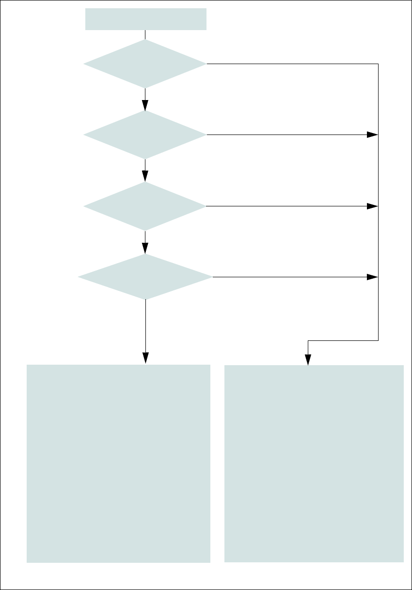
Fig. 2.5 - 6 EMERGENCY STOP loops
Start button pressed.
No
No
Yes
No
No
Yes
Yes
2
Active
Safety cutoff Off
Voltage
Y axis 0 V
X axis 0 V
Star axis 0 V
DP axis 42V-
Z axis (C&P, TH) 42 V-
Z axis (CPP / CPP M) 0 V-
Active
PCB conveyor No
Lifting table No
PCB clamp No
Width adjustment No
Tape cutter No
COT insert Yes
Yes
Compressed
air min. 0.5 MPa
(5.0 bar)?
EMERGENCY STOP button
pressed?
- Protective cover open?
Component trolley
EMERGENCY STOP circuit
interrupted?
2
Active
Safety cutoff On
Voltage
Y axis 300 V-
X axis 300 V-
Star axis 160 V-
DP axis 42 V-
Z axis (C&P, TH) 42 V-
Z axis (CPP / CPP M) 160 V-
Active
PCB conveyor Yes
Lifting table Yes
PCB clamp Yes
Width adjustment Yes
Tape cutter Yes
COT insert Yes
2 Operational safety User manual SIPLACE TX-Series
2.5 Safety features From software version 713.0 Edition 01/2020
92
2.5.3.2 Enabling the EMERGENCY STOP
If problems occur, the SIPLACE TX can be stopped by pressing the EMERGENCY STOP button.
An EMERGENCY STOP can be triggered by:
– Pressing one of the EMERGENCY STOP buttons on the placement machine
In these cases, the safety cutoffs are triggered and the power contactors will be switched off within
100 ms or 500 ms (STOP category 1, controlled shutdown with interruption of power supply during
downtime).
2.5.3.3 Resetting an EMERGENCY STOP
To reset an EMERGENCY STOP, unlock the EMERGENCY STOP button.
Find out the reason why the EMERGENCY STOP button triggered.
Remove the cause.
Unlock the relevant EMERGENCY STOP button.
2.5.3.4 Resetting the lock
Close the open protective cover.
2.5.3.5 Triggering the lock
Opening the protective cover.