00197975-06_UM_TX-Serie_EN.pdf - 第167页
User manual SIPLACE TX-Series 3 Technical data and assemblies From software version 713.0 Edition 01/2020 3.8 SIPLACE tape fee d er modules for SIPLACE TX-Series 167 3.8.5.2 Safety instructions 3.8.5.3 T echnical data 3 …
3 Technical data and assemblies User manual SIPLACE TX-Series
3.8 SIPLACE tape feeder modules for SIPLACE TX-Series From software version 713.0 Edition 01/2020
166
3.8.5 SIPLACE PowerConnector X
Item no. 00141420-xx SIPLACE PowerConnector X
3
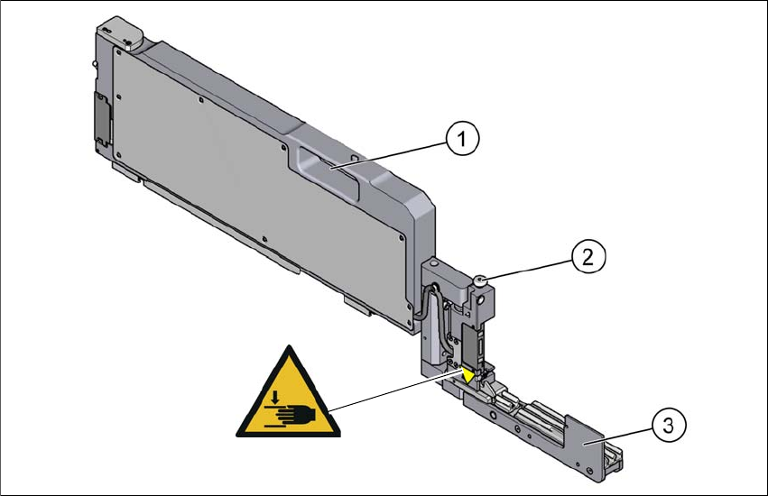
Fig. 3.8 - 6 SIPLACE PowerConnector X
(1) Handle
(2) Unlocking button for extender arm and feeder
(3) Extender arm (in work position)
Item W 024, item no. 03155346-01
3.8.5.1 Description
The SIPLACE PowerConnector X helps to resolve problems connected to SIPLACE X feeder
modules in the placement machine, without the need to stop the production process.
For a detailed description, see the SIPLACE PowerConnector X user guide, [item no. 00198772-
01-xx.]
W 024
User manual SIPLACE TX-Series 3 Technical data and assemblies
From software version 713.0 Edition 01/2020 3.8 SIPLACE tape feeder modules for SIPLACE TX-Series
167
3.8.5.2 Safety instructions
3.8.5.3 Technical data
3
3
3
3
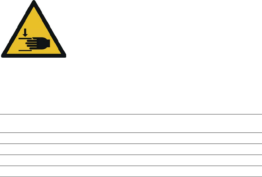
Warning about hand injuries
There is a risk of injury to hands when folding the extender arm up
into the park position.
When folding up the extender arm, make sure that you do not
trap your hand between the extender arm and the
S
IPLACE PowerConnector X.
Length 648.4 mm (folded in)
866.9 mm (folded out)
Width 34.4 mm
Height 188.4 mm
Occupied locations 3
Weight 3.2 kg
3 Technical data and assemblies User manual SIPLACE TX-Series
3.9 Component trolley From software version 713.0 Edition 01/2020
168
3.9 Component trolley
Two SIPLACE TX-Series component trolleys can be docked onto SIPLACE TX-Series placement
machines.
3
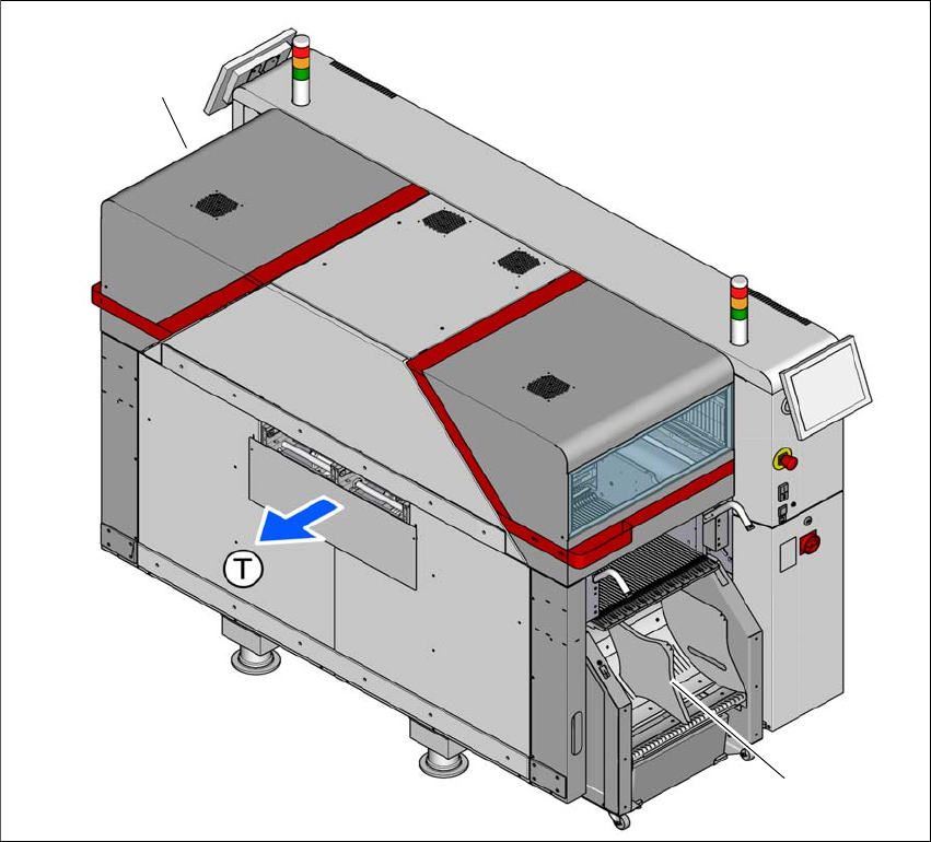
Fig. 3.9 - 1 Component trolley locations
(1) Location 1
(2) Location 2 with optional 7" tape reel holder
(T) Direction of PCB transport
The component trolleys are stand-alone modules that can be set up with feeders at an external
setup area. This means that the production process only has to be interrupted briefly in order to
change the component trolley. The component trolley has 5 holders in total. Each tape reel holder
can accommodate 2 tape reels, so that up to ten 13" (optional 7") tape reels can be positioned
above the tape container.
(2)
(1)