00197975-06_UM_TX-Serie_EN.pdf - 第144页
3 Technical data and assemblie s User manual SIPLACE TX-Series 3.6 Gantry system From software version 713.0 Edition 01/2020 144 3.6.4 Y axis structure 3 Fig. 3.6 - 4 Y axis structure The Y axis es sentially consis ts of…
User manual SIPLACE TX-Series 3 Technical data and assemblies
From software version 713.0 Edition 01/2020 3.6 Gantry system
143
3.6.3 Gantry structure
3
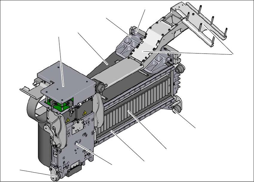
Fig. 3.6 - 3 Gantry structure - view of head mount
(1) Head boards
(2) Gantry arm
(3) Y linear motor with fixed bearing (primary part)
(4) Mount for conversion board and trailing cable holder
(5) End position bumper (4x)
(6) Guidance system with permanent magnet (secondary part of the X linear motor)
(7) Length measurement system
(8) Head mount with X axis linear motor (primary part)
(9) Sensor module (for SIPLACE TX micron only)
(4)
(3)
(1)
(5)
(2)
(6)
(7)
(5)
(8)
(9)
3 Technical data and assemblies User manual SIPLACE TX-Series
3.6 Gantry system From software version 713.0 Edition 01/2020
144
3.6.4 Y axis structure
3
Fig. 3.6 - 4 Y axis structure
The Y axis essentially consists of the following main modules:
(1) Y linear motors (primary part) on the X axis with fixed and loose bearing mounted
(2) Permanent magnet (secondary part of the X-axis linear motor)
(3) Linear distance measuring system
(4) Guidance system
(1)
(4)
(3)
(2)
(4)
User manual SIPLACE TX-Series 3 Technical data and assemblies
From software version 713.0 Edition 01/2020 3.7 PCB conveyor system
145
3.7 PCB conveyor system
3.7.1 Description
The PCB conveyors are designed as three-part conveyors with input, processing and output con-
veyor sections. The two areas, input conveyor and output conveyor, serve as buffer zones for the
printed circuit boards.
The conveyor belts are driven by brushless DC motors. Light barriers monitor and control trans-
portation of the boards. Once the board has reached the placement area and has passed the light
barriers, it is braked. A laser light barrier records the position of the board. As soon as the circuit
board has reached its target position, the conveyor belt is stopped and the board is clamped from
below.
The distance between the top of the PCB and the placement head thus remains unchanged for
each PCB, and is not dependent on the thickness of the PCB. The placement rate is thus inde-
pendent of the PCB thickness. The PCB fiducial centering can also be optimized. Since the dis-
tance between the PCB surface and the PCB camera remains the same, the PCB camera is
always focussed on the PCB surface with the same sharpness. The PCB fiducial contours are op-
timally mapped on the CCD chip of the PCB camera.
The width of the circuit board conveyor is set and monitored by an integral control circuit. It can
be selected by calling up the program. The control electronics activate the drive motor until the
required width has been reached. The width adjustment is therefore independent of other machine
components.
The conveyor height can be selected on the placement machine to allow them to be integrated
into lines with a conveyor height of, 900, 930 or 950 mm. The standard height is 930 mm.
The communication between the PCB conveyors of the individual placement machines takes
places via the SMEMA interface.