00197975-06_UM_TX-Serie_EN.pdf - 第198页
4 Setting up and commissioning Us er manual SIPLACE TX-Series 4.5 Setting up the placement mac hine From software version 713.0 Edition 01/2020 198 4.5 Setting up the placement machine 4.5.1 Fitting att ached part s The …

User manual SIPLACE TX-Series 4 Setting up and commissioning
From software version 713.0 Edition 01/2020 4.4 Infrastructure at the installation location
197
F9 Gantry 2 6,3 24
F10 Internal 6,3 24
F11 CSB signal 6,3 24
F12 CSB supply 6,3 24
F13 -- -- --
F14 Head 1 6,3 42
F15 Head 2 6,3 42
F16 Conveyor drives 10,0 42
F19 Gantry 1 6,3 160
F20 Gantry 2 6,3 160
F21 Vision 6,3 42
F22 FCU 1 10 27
F23 FCU 2 10 27
Fuse Components Electricity
[A]
Voltage [V]
4 Setting up and commissioning User manual SIPLACE TX-Series
4.5 Setting up the placement machine From software version 713.0 Edition 01/2020
198
4.5 Setting up the placement machine
4.5.1 Fitting attached parts
The placement machine is delivered with the monitor and indicator lamp dismantled. To fit the in-
dicator lamps and the monitors, proceed as follows.
4.5.1.1 Fitting the indicator lamp
Insert the indicator lamp into the hole until the lamp tube projects sufficiently into the terminal
beneath.
Pull the connector slightly out of the lamp base.
Plug the connector into the bottom of the upper section of the lamp.
Turn the signaling lamp, until it engages.
4.5.1.2 Fixing the monitors
Use the fastening screws to fix the monitor to the monitor mount and then connect the cable.
Check the cable connections.
Fasten the monitor cable to the monitor with a strain relief.
User manual SIPLACE TX-Series 4 Setting up and commissioning
From software version 713.0 Edition 01/2020 4.5 Setting up the placement machine
199
4.5.2 Removing the shipping braces from the gantries
The gantries are secured with a shipping brace in both the X and Y directions. After transportation
of the placement machine, remove the shipping braces.
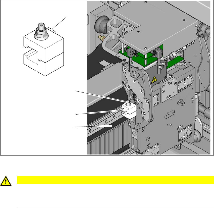
4.5.2.1 Removing the shipping brace on the X axis
4
Fig. 4.5 - 1 Shipping brace on the X axis
4
Loosen the screw (1) on the shipping brace (2) so that the shipping brace can be easily taken
off the linear guide.
4
CAUTION
Do not damage the scale!
The scale is located under the shipping brace (2).
Make sure that the scale (3) under the shipping brace is not damaged.
(1)
(3)
(2)
(4)