00197182-04_AI_Prepare_Kit_SX12_de_en.pdf - 第40页
4 Anhang 4.2 Platinenbeschreibungen Assembly Instructions / Montageanleitung SIPLACE SX1/SX2 Prepare Kit 04/2017 40 Sicherungen [03104070-01] Sicherung Beschreibung F1 27V DC MGCU 1 F2 27V DC MGCU 2 F3 27V DC MGCU 3 F4 2…
Assembly Instructions / Montageanleitung SIPLACE SX1/SX2
Prepare Kit 04/2017
4 Anhang
4.2 Platinenbeschreibungen
39
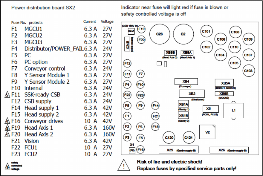
Abb.34: Übersicht Sicherungen
●
Sicherung 5x20mm T6,3A 400VDC [03133256-xx] (ersetzt: [03078843-xx])
●
Feinsicherung 5x20 / T 10A [03010627-xx]

4 Anhang
4.2 Platinenbeschreibungen
Assembly Instructions / Montageanleitung SIPLACE SX1/SX2
Prepare Kit 04/2017
40
Sicherungen [03104070-01]
Sicherung Beschreibung
F1 27V DC MGCU 1
F2 27V DC MGCU 2
F3 27V DC MGCU 3
F4 24V DC Distributor
F5 27V DC IBASE PC
F6 27V DC Option 3D-Koplan PC
F7 24V DC Transport
F8 27V DC Portal 1
F9 27V DC Portal 2
F10 24V DC Internal – C (Interne Spannung CSB – Not-Aus)
F11 24V DC SSK_Ready
F12 24V DC Safety Supply
F14 42V DC Portalkabel 1 MHCU
F15 42V DC Portalkabel 2 MHCU
F16 42V DC Transportantrieb
F17 27V DC Absicherung 27V/24V DCDC
F18 Reserve
F19 160V DC Kopfachsen Portal 1
F20 160V DC Kopfachsen Portal 2
F21 Reserve
F22 27V DC FCU 1
F23 27V DC FCU 2
Stecker [03104070-01]
Stecker Bezeichnung Anschluss
X1 Anschluss Masse "Verteil- und Sicherungsplatine" von Haupterdungsklemme
XB1A Portal 1 – 24V & Signale zum Portalkabel G1
XB1B Portal 2 – 24V & Signale zum Portalkabel G2
X2 Diagnostic serial interface (Diagnose Info F&D) zum IOCU2 X11 Sektor 2
X5 FCU 1/2 – 27V DC zum FCU1(X111)/2 (X131)
XB5A GCU 1/2 supply zum MGCU1 / 2
XB5B GCU3 zum MGCU3
XB8A Portal 1 – 160V DC zum Portalkabel G1 Kopf
XB8B Portal 2 – 160V DC zum Portalkabel G2 Kopf
X24A Star Voltage – 160V von CSB
X24B Safety control signals to FDB – DC42V IN/OUT zum CSB
X25 DC 42V IN von AC/DC-Konverter
X26 DC 27V IN von AC/DC-Konverter
XB2 Power Distributor & PC 3D-Sensor – 27V/24V/42V zum Distributor Sektor 2
XB4 Transport zum Transport
41
Assembly Instructions / Montageanleitung SIPLACE SX1/SX2
Prepare Kit 04/2017
Contents
Contents
1 Introduction.. 43
1.1 Safety Instructions.. 43
1.1.1 Conventions for the Use of Safety Instructions and Symbols.. 43
1.1.2 Safety Instructions for Working with Strong Magnetic Fields.. 44
1.1.3 Safety Instructions for the Power Supply (Without SMPS).. 44
1.1.4 Safety Instructions for the Power Supply (With SMPS).. 45
1.1.5 Safety instructions for the compressed air supply.. 47
1.1.6 Safety Instructions for the Gantry.. 47
1.1.7 Safety Instructions on Hazardous Materials.. 47
1.2 Preparatory Work..... 48
1.3 Other Instructions.. 50
1.3.1 Environmentally-Friendly Disposal of Materials and Components.. 50
1.3.2 Use of Original SIPLACE Accessories and Spare Parts.. 51
1.3.3 ESD Guidelines.. 51
1.3.3.1 Definition of ESD.. 51
1.3.3.2 Important Measures to Protect Against Static Charging.. 51
1.3.3.3 Handling ESD Modules.. 51
1.3.3.4 Measurements and Modifications to ESD Modules.. 51
1.3.3.5 Dispatching ESD Modules.. 52
1.3.4 Release History.. 52
2 Brief Description.. 53
2.1 Overview.. 53
2.1.1 Machine Variants.. 53
2.1.2 Differentiation between the Prepare Kits.. 54
2.2 Scope of Delivery.. 54
2.3 Tools and Equipment Required.. 56
2.4 Required Working Time.. 56
3 Fitting the Prepare Kit.. 57
3.1 Preparations at the Machine.. 57
3.2 Preparing the Trailing Cable Interface.. 58
3.3 Preparing and Fitting the GCU.. 59
3.4 GCU cabling.. 61
3.5 Fitting the Trailing Cable.. 65
3.6 Fitting the Magnets.. 69
3.7 Fitting the End Stop and Preparing the Prepare Kit Case.. 70
3.8 Final Work.. 71
4 Appendix.. 73
4.1 Excerpts from the Service Manual.. 73
4.1.1 GCU (Up To Machine No. Mxxxx).. 73
4.1.2 MGCU (From Machine No. Nxxxx to Oxxxx).. 74
4.1.3 MGCU - Full Mode (From Machine No. Pxxxx).. 75
4.2 Description of Boards.. 76
4.2.1 Distribution and Fusing Assembly [03118286-xx].. 76