00197182-04_AI_Prepare_Kit_SX12_de_en.pdf - 第66页
3 Fitting the Prepare Kit 3.5 Fitting the Trailing Cable Assembly Instructions / Montageanleitung SIPLACE SX1/SX2 Prepare Kit 04/2017 66 Fig.20: Pneumatic hoses Connection for compressed air line in the machine ► Fix th…
Assembly Instructions / Montageanleitung SIPLACE SX1/SX2
Prepare Kit 04/2017
3 Fitting the Prepare Kit
3.5 Fitting the Trailing Cable
65
3.5 Fitting the Trailing Cable
Parts, equipment and tools
●
1x GR Y trailing cable vacuum complete [03075584-xx]
●
C-parts Y-Trailing Cable vacuum [03075588-xx]
– 4x QS-10 connector [03075789-xx]
– 4x QSC-10H plug [00324874-xx]
– 4x standoff (spacer bolt) M4x10 [03023606-xx]
●
1x plastic case [03081445-xx]
– 1x heat-shrinkable hose [00326917-xx]
– 1x trailing cable bracket for gantry 2 complete [03076756-xx]
●
Loctite 241 [02101037‑xx]
Installation
► Connect the four QS-10 connectors to the end of the trailing cable, which will later be connec-
ted to the gantry. Seal the connectors with the four QSC-10 plugs.
► Pull the heat-shrinkable hose over the trailing cable to prevent damage during assembly.
► Carefully place the trailing cable into the machine.
► Check the Y connectors, which should be attached to pneumatic hoses 1 and 4.
► Connect the blue pneumatic hose from the machine to the other side of the Y connection.
► Check the pneumatic hoses 2 and 3 to make sure that these have each been fitted with a con-
nector and plug.
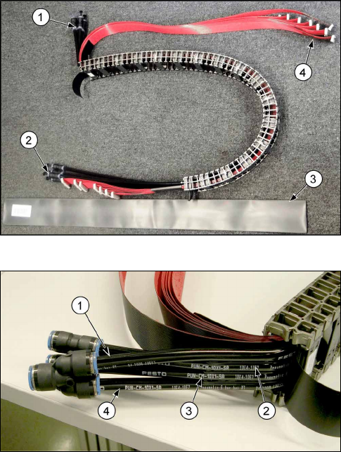
Fig.18: Trailing cable
Preparing the trailing cable
1. Compressed air connection present
2. Fit the connectors and plugs.
3. Pull the heat-shrinkable hose over the trailing
cable.
4. Connections for trailing cable interface and hot-
link adapter.
Fig.19: Pneumatic hoses in the trailing cable
Labeling for compressed air line in the trailing cable
●
Make sure that the pneumatic hoses are labeled
as marked in the image!
3 Fitting the Prepare Kit
3.5 Fitting the Trailing Cable
Assembly Instructions / Montageanleitung SIPLACE SX1/SX2
Prepare Kit 04/2017
66
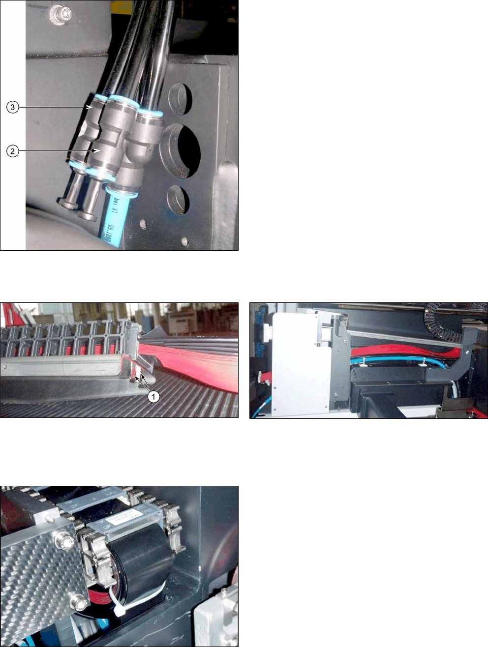
Fig.20: Pneumatic hoses
Connection for compressed air line in the machine
► Fix the two spacer bolts M4x10 to the trailing cable cover with the trailing cable and then
secure them with Loctite 241.
Fig.21: Fixture for trailing cable
Fig.22: Running the trailing cable
► Run the flat ribbon cables around the trailing cable cover and thread them through to the trail-
ing cable interface.
► Fit the trailing cable cover to the machine base.
Fig.23: Fixing the protective tape onto the trailing cable
► Fix the protective tape onto the trailing cable with
a cable tie.
Assembly Instructions / Montageanleitung SIPLACE SX1/SX2
Prepare Kit 04/2017
3 Fitting the Prepare Kit
3.5 Fitting the Trailing Cable
67
► Connect the flat ribbon cable to the trailing cable interface and the hotlink adapter.
- Flat ribbon cable X3cg to the hotlink adapter
- Flat ribbon cable X1a – X7a on the trailing cable interface
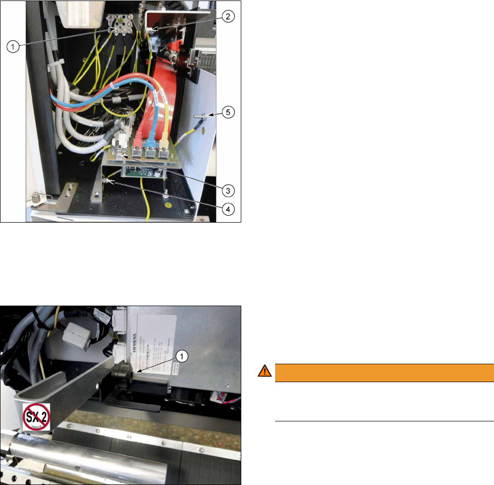
Fig.24: Ground cable connection
► Screw all ground cables to the earthing panel (1).
- Trailing cable cover (2) -> earthing panel
- Trailing cable interface board (3) -> earthing
panel
- Trailing cable interface support (4) -> earthing
panel
- Side part (5) -> earthing panel
- Ground cable for GCU carrier -> earthing panel
► Attach the side cover to the trailing cable with two screws.
► After completing all work, check that all cables have been run correctly and fit them into place
with cable ties, where needed.
If the machine is not fitted with a second gantry, you have to secure the trailing cable.
Fig.25: Trailing cable bracket
1. Fixture for trailing cable bracket
► Use the star screw(1) to fix the trailing cable
bracket to the GCU carrier.
WARNING!
Gantry crash!
The trailing cable bracket must be removed if
you fit a second gantry!
.