00197182-04_AI_Prepare_Kit_SX12_de_en.pdf - 第64页
3 Fitting the Prepare Kit 3.4 GCU cabling Assembly Instructions / Montageanleitung SIPLACE SX1/SX2 Prepare Kit 04/2017 64 Fig.16: Switching unit connections (see also 4.2.1 "Distribution and Fusing Assembly [031182…
Assembly Instructions / Montageanleitung SIPLACE SX1/SX2
Prepare Kit 04/2017
3 Fitting the Prepare Kit
3.4 GCU cabling
63
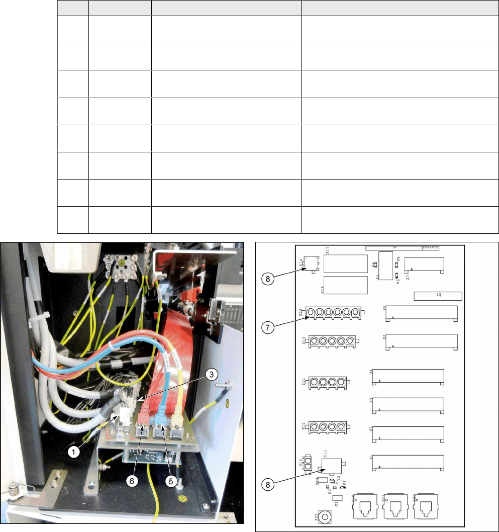
► Place the cable tree with the following cables into the machine. Begin by running from the top
(GCU) to the bottom (trailing cable interface -> switching unit in power supply).
► The ground cable from the main cable [03068133-xx] is connected directly to the GCU.
Pos. Item No. Cable designation Connector designation
1 03055221-
xx
Cable for motor Y1 GCU X3up to trailing cable interface X10ca
2 03068134-
xx
Cable 24V power fail GCU GCU X1up to switching unit XB5bqy
3 03055223-
xx
Cable for motor Y2 GCU X4up to trailing cable interface X11ca
4 03068133-
xx
Cable for power supply to main
axes
GCU X2up to pre-/discharge assembly
X22B.CSB
5 03055226-
xx
Blue CAT5 cable GCU X73Uuc to trailing cable interface
X20ca
6 03055225-
xx
Red CAT5 cable GCU X73Ouc to trailing cable interface
X20ca
7 03068135-
xx
Voltage supply 150VDC Trailing cable interface X15ca to switching
unit XB8bqy
8 03068135-
xx
Power fail 24VDC / camera illu-
mination
Trailing cable interface X13ca / X14ca to
switching unit XB1bqy
Fig.14: Trailing cable interface
Fig.15: Trailing cable interface connections
3 Fitting the Prepare Kit
3.4 GCU cabling
Assembly Instructions / Montageanleitung SIPLACE SX1/SX2
Prepare Kit 04/2017
64
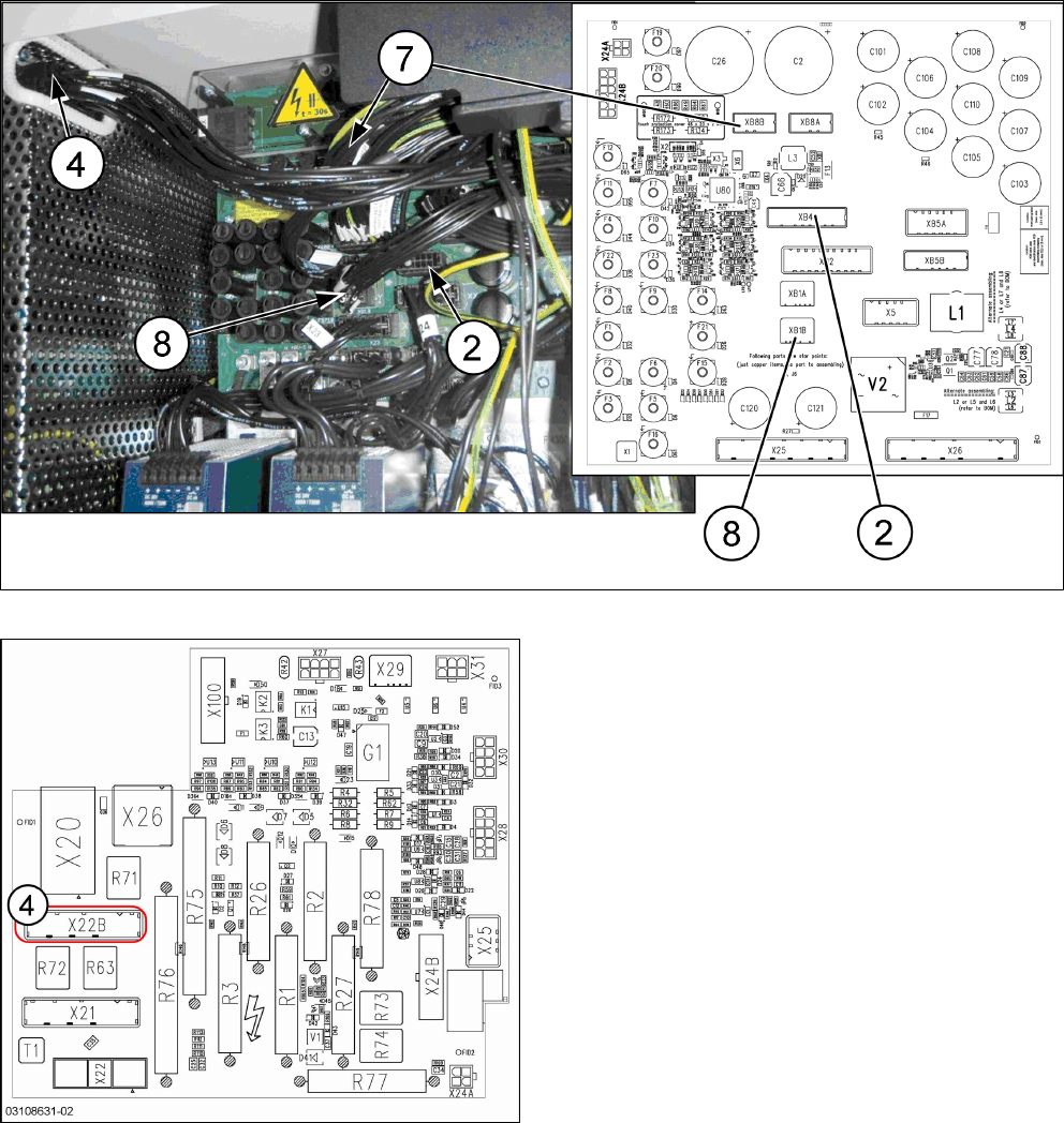
Fig.16: Switching unit connections (see also 4.2.1 "Distribution and Fusing Assembly [03118286-xx]" [
}
76])
Fig.17: Pre-/discharge assembly [03108631-xx] (CSB)
► Connect the ground cable from the main cable
[03068133-xx] to the ground terminal in the
switching unit.
► Fix the cable tree to the power supply strain
relief, using two cable ties.
► Place the cable tree excess on the left, next to
the transformer in the machine base.
► The ground cable [03055212-xx] (1m length) is
connected directly to the GCU support and to the
ground surface in the machine.
Assembly Instructions / Montageanleitung SIPLACE SX1/SX2
Prepare Kit 04/2017
3 Fitting the Prepare Kit
3.5 Fitting the Trailing Cable
65
3.5 Fitting the Trailing Cable
Parts, equipment and tools
●
1x GR Y trailing cable vacuum complete [03075584-xx]
●
C-parts Y-Trailing Cable vacuum [03075588-xx]
– 4x QS-10 connector [03075789-xx]
– 4x QSC-10H plug [00324874-xx]
– 4x standoff (spacer bolt) M4x10 [03023606-xx]
●
1x plastic case [03081445-xx]
– 1x heat-shrinkable hose [00326917-xx]
– 1x trailing cable bracket for gantry 2 complete [03076756-xx]
●
Loctite 241 [02101037‑xx]
Installation
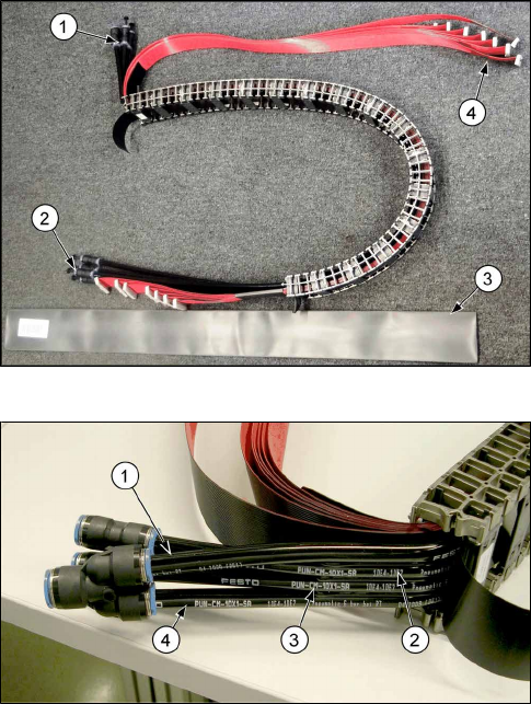
► Connect the four QS-10 connectors to the end of the trailing cable, which will later be connec-
ted to the gantry. Seal the connectors with the four QSC-10 plugs.
► Pull the heat-shrinkable hose over the trailing cable to prevent damage during assembly.
► Carefully place the trailing cable into the machine.
► Check the Y connectors, which should be attached to pneumatic hoses 1 and 4.
► Connect the blue pneumatic hose from the machine to the other side of the Y connection.
► Check the pneumatic hoses 2 and 3 to make sure that these have each been fitted with a con-
nector and plug.
Fig.18: Trailing cable
Preparing the trailing cable
1. Compressed air connection present
2. Fit the connectors and plugs.
3. Pull the heat-shrinkable hose over the trailing
cable.
4. Connections for trailing cable interface and hot-
link adapter.
Fig.19: Pneumatic hoses in the trailing cable
Labeling for compressed air line in the trailing cable
●
Make sure that the pneumatic hoses are labeled
as marked in the image!