00197182-04_AI_Prepare_Kit_SX12_de_en.pdf - 第57页
Assembly Instructions / Montageanleitung SIPLACE SX1/SX2 Prepare Kit 04/2017 3 Fitting the Prepare Kit 3.1 Preparations at the Machine 57 3 Fitting the Prepare Kit 3.1 Preparations at the Machine ► Switch off the machine…
2 Brief Description
2.3 Tools and Equipment Required
Assembly Instructions / Montageanleitung SIPLACE SX1/SX2
Prepare Kit 04/2017
56
2.3 Tools and Equipment Required
●
Torque wrench 6Nm with socket-head adapter SW 4 and 8
●
Spacer for Y magnets [03065304-xx]
●
Emergency kit for magnets:
– Plastic wedges [03097870-xx]
– Copper hammers [03097897-xx]
Circuit diagram folder for your machine:
●
Detailed circuit diagrams folder for SIPLACE SX1/SX2/DX1/DX2 (up to Kxxxx)
[DE+EN:00196475-xx]
●
Detailed circuit diagrams folder for SIPLACE SX1/SX2 V2 (from Lxxxx)
[DE+EN:00196979-xx]
●
Detailed circuit diagrams folder for SIPLACE SX1/SX2 V2 (from Nxxxx)
[DE+EN:00197899-xx]
2.4 Required Working Time
The complete installation will take approx. 3 hours.
The machine standstill time is approx. 4 hours.
Assembly Instructions / Montageanleitung SIPLACE SX1/SX2
Prepare Kit 04/2017
3 Fitting the Prepare Kit
3.1 Preparations at the Machine
57
3 Fitting the Prepare Kit
3.1 Preparations at the Machine
► Switch off the machine, disconnect it from the power supply and secure it to prevent
unauthorized reactivation. Observe the instructions in section 1.2 "Preparatory Work..." [}48].
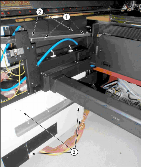
► Remove the changeover table from location 2.
Fig.6: Removing the covers
1. Side cover
2. Trailing cable cover
3. Cover on infrastructure box
► Remove the side cover(1) and the trailing cable
cover(2) from the left side of the location.
► Remove the inner cover on the infrastructure box
(3).
3 Fitting the Prepare Kit
3.2 Preparing the Trailing Cable Interface
Assembly Instructions / Montageanleitung SIPLACE SX1/SX2
Prepare Kit 04/2017
58
3.2 Preparing the Trailing Cable Interface
Parts, equipment and tools
●
Support for trailing cable interface [03068747-xx]
●
Vision hotlink adapter [03050555-xx]
●
Trailing cable interface [03064127-xx]
●
2x ground cable 0.5 m [03055213-xx] from cable set for gantry 2 [03052290-xx]
●
C-parts trailing cable interface support [03094645-xx]
– 10x socket-head screws M3x6 [03042541-xx]
– 2x lens head screws M4x6 [03046903-xx]
– 1x socket-head screws M5x8 [03042559-xx]
– 1x serrated lock washer 5-FSt [03047704-xx]
Installation
The support for the trailing cable interface and the hotlink adapter should be prepared with the
spacer bolts at the top and bottom and with a ground screw.
► First fit the trailing cable interface support with the hotlink adapter, by fixing it from below to
the bracket (4x M3x6 mm socket-head screws).
► Now fit the trailing cable interface from above, onto the support.
(6x M3x6 mm socket-head screws)
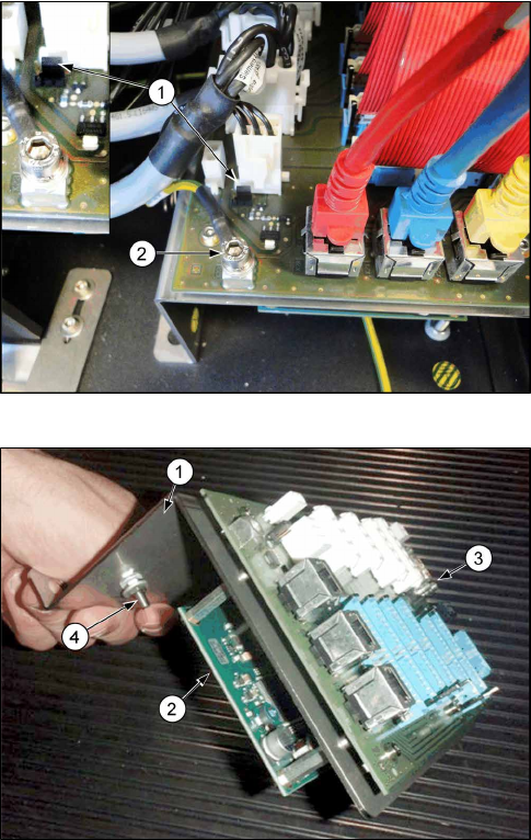
Fig.7: Trailing cable interface
1. Jumper for trailing cable interface
2. Ground screw for trailing cable interface
► Fix the ground cable 0.5 m to the support, using
the existing ground screw.
► Fix the ground cable 0.5 m directly to the trailing
cable interface, using the socket-head screw
M5x8 mm and the serrated lock washer 5-FSt.
► Set the jumper as shown in the image.
Fig.8: Trailing cable interface with support
1. Trailing cable interface support
2. Hotlink adapter
3. Trailing cable interface
4. Ground screw for trailing cable interface support
► Attach the pre-fitted trailing cable interface sup-
port, by screwing it with the lens head screws
(M4x6 mm) into the relevant pre-drilled holes
above the infrastructure box.
► Both ground cables are attached to the earthing
panel on the machine. (spare screws and contact
discs can be found on the earthing panel)