00197182-04_AI_Prepare_Kit_SX12_de_en.pdf - 第63页
Assembly Instructions / Montageanleitung SIPLACE SX1/SX2 Prepare Kit 04/2017 3 Fitting the Prepare Kit 3.4 GCU cabling 63 ► Place the cable tree with the following cables into the machine. Begin by running from the top (…
3 Fitting the Prepare Kit
3.4 GCU cabling
Assembly Instructions / Montageanleitung SIPLACE SX1/SX2
Prepare Kit 04/2017
62
Installation
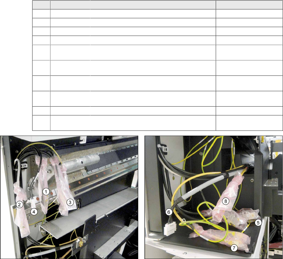
► Connect the existing cables in the machine to the trailing cable interface and GCU.
► Begin with the CAN bus cables and pay attention to the labeling!
Pos. Item No. Cable designation Connector designation
1 03055207- xx Black CAT5 cable GCU X74Uuc
2 03055208- xx Gray CAT5 cable GCU X72Uuc
3 03052208- xx CAN bus cable GCU X1Ouc
3 03055200- xx CAN bus cable GCU X1Uuc
5 03052208- xx CAN bus cable Trailing cable interface
X17ca
5 03055200- xx CAN bus cable Trailing cable interface
X18ca
6 03055227- xx Voltage supply X motor gantry 2 Trailing cable interface
X12ca
7 03055230- xx Yellow CAT5 cable sensor bus X Trailing cable interface
X22ca
8 03071336- xx Oranges CAT5 cable, hotlink cable camera Hotlink adapter X1cg
4 03071336- xx Voltage supply to fan Is already connected!
X1hm
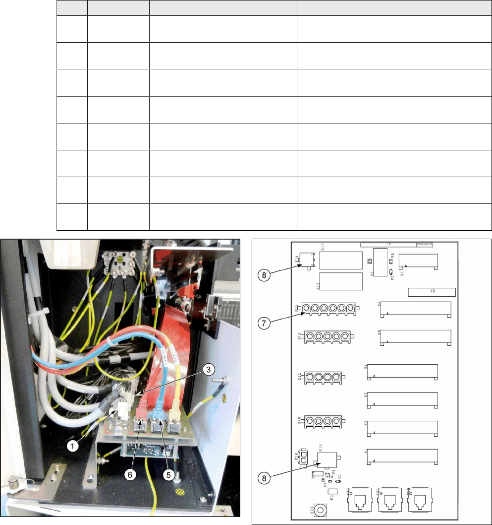
Fig.12: Connecting the cable to GCU 3 Fig.13: Connecting the cable to the trailing cable interface and
the hotlink adapter
► Connect all cables from (1) to (4) to the GCU 3 at location 2.
► Connect all cables from (5) to (8) to the trailing cable interface and the hotlink adapter.
Assembly Instructions / Montageanleitung SIPLACE SX1/SX2
Prepare Kit 04/2017
3 Fitting the Prepare Kit
3.4 GCU cabling
63
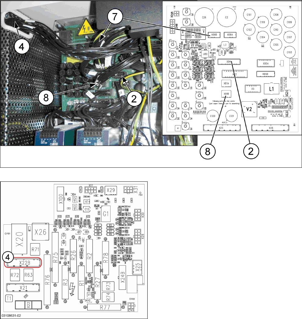
► Place the cable tree with the following cables into the machine. Begin by running from the top
(GCU) to the bottom (trailing cable interface -> switching unit in power supply).
► The ground cable from the main cable [03068133-xx] is connected directly to the GCU.
Pos. Item No. Cable designation Connector designation
1 03055221-
xx
Cable for motor Y1 GCU X3up to trailing cable interface X10ca
2 03068134-
xx
Cable 24V power fail GCU GCU X1up to switching unit XB5bqy
3 03055223-
xx
Cable for motor Y2 GCU X4up to trailing cable interface X11ca
4 03068133-
xx
Cable for power supply to main
axes
GCU X2up to pre-/discharge assembly
X22B.CSB
5 03055226-
xx
Blue CAT5 cable GCU X73Uuc to trailing cable interface
X20ca
6 03055225-
xx
Red CAT5 cable GCU X73Ouc to trailing cable interface
X20ca
7 03068135-
xx
Voltage supply 150VDC Trailing cable interface X15ca to switching
unit XB8bqy
8 03068135-
xx
Power fail 24VDC / camera illu-
mination
Trailing cable interface X13ca / X14ca to
switching unit XB1bqy
Fig.14: Trailing cable interface
Fig.15: Trailing cable interface connections
3 Fitting the Prepare Kit
3.4 GCU cabling
Assembly Instructions / Montageanleitung SIPLACE SX1/SX2
Prepare Kit 04/2017
64
Fig.16: Switching unit connections (see also 4.2.1 "Distribution and Fusing Assembly [03118286-xx]" [
}
76])
Fig.17: Pre-/discharge assembly [03108631-xx] (CSB)
► Connect the ground cable from the main cable
[03068133-xx] to the ground terminal in the
switching unit.
► Fix the cable tree to the power supply strain
relief, using two cable ties.
► Place the cable tree excess on the left, next to
the transformer in the machine base.
► The ground cable [03055212-xx] (1m length) is
connected directly to the GCU support and to the
ground surface in the machine.