00197182-04_AI_Prepare_Kit_SX12_de_en.pdf - 第68页
3 Fitting the Prepare Kit 3.5 Fitting the Trailing Cable Assembly Instructions / Montageanleitung SIPLACE SX1/SX2 Prepare Kit 04/2017 68 Fig.26: Fixture for trailing cable ► Clamp the trailing cable into the bracket, as…
Assembly Instructions / Montageanleitung SIPLACE SX1/SX2
Prepare Kit 04/2017
3 Fitting the Prepare Kit
3.5 Fitting the Trailing Cable
67
► Connect the flat ribbon cable to the trailing cable interface and the hotlink adapter.
- Flat ribbon cable X3cg to the hotlink adapter
- Flat ribbon cable X1a – X7a on the trailing cable interface
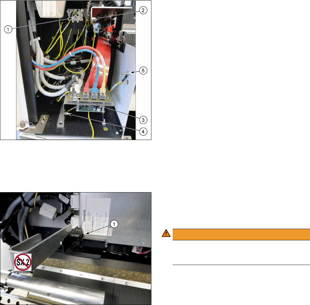
Fig.24: Ground cable connection
► Screw all ground cables to the earthing panel (1).
- Trailing cable cover (2) -> earthing panel
- Trailing cable interface board (3) -> earthing
panel
- Trailing cable interface support (4) -> earthing
panel
- Side part (5) -> earthing panel
- Ground cable for GCU carrier -> earthing panel
► Attach the side cover to the trailing cable with two screws.
► After completing all work, check that all cables have been run correctly and fit them into place
with cable ties, where needed.
If the machine is not fitted with a second gantry, you have to secure the trailing cable.
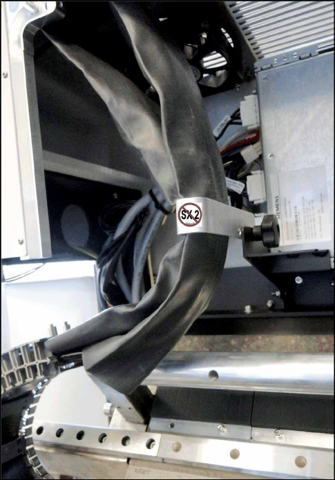
Fig.25: Trailing cable bracket
1. Fixture for trailing cable bracket
► Use the star screw(1) to fix the trailing cable
bracket to the GCU carrier.
WARNING!
Gantry crash!
The trailing cable bracket must be removed if
you fit a second gantry!
.
3 Fitting the Prepare Kit
3.5 Fitting the Trailing Cable
Assembly Instructions / Montageanleitung SIPLACE SX1/SX2
Prepare Kit 04/2017
68
Fig.26: Fixture for trailing cable
► Clamp the trailing cable into the bracket, as
shown in the diagram.
► Connect the compressed air line for the second gantry that is located in the infrastructure box
1 to the compressed air supply.
Assembly Instructions / Montageanleitung SIPLACE SX1/SX2
Prepare Kit 04/2017
3 Fitting the Prepare Kit
3.6 Fitting the Magnets
69
3.6 Fitting the Magnets
Parts, equipment and tools
●
4x secondary part (Y magnets) [03064172-xx]
●
1x C parts set for secondary parts [03094646-xx]
– 14x socket-head screws M5x18 [03080697-xx]
●
1x fit-up aid Y magnets [03065304-xx]
●
1x torque wrench with socket-head adapter
Installation
To guarantee gantry modularity on the SX1 prepared machine, you need to fit two Y magnets each
on the left and right side of the Y axis, in preparation for later installation of a second gantry.r
DANGER
Observe the safety instructions when handling magnets!
► Do not remove the magnet cover until the magnet has been screwed firmly into place!
► Remove the end position buffers from both sides of the Y axis. This enables you to insert the
magnets at the sides.
► Slowly and carefully push the magnets onto the machine frame of the Y axis.
NOTICE
Observe the polarity
► Make sure that the magnet poles are correct (north and south)!
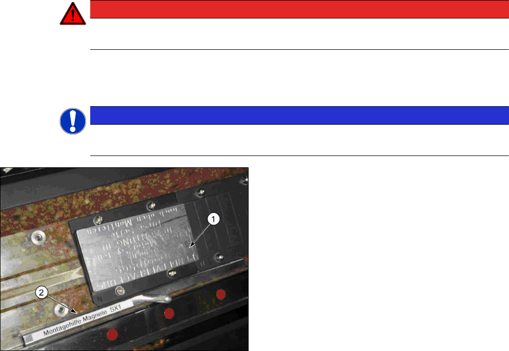
Fig.27: Magnet with cover
1. Magnet with cover
2. Assembly gauge (Y magnet spacing)
► Use the assembly gauge to align the magnet
plate and fix the first magnets into place with four
screws of type M5x18 and a force of 6Nm.
► The second magnet is only fixed with three
screws. The bottom left screw is not needed!
► Fit the end position buffers. Use the long buffers for SX1 machines.
See also the "Gantry Modularity Assembly Instructions" [00196626-xx].