00197182-04_AI_Prepare_Kit_SX12_de_en.pdf - 第70页
3 Fitting the Prepare Kit 3.7 Fitting the End Stop and Preparing the Prepare Kit Case Assembly Instructions / Montageanleitung SIPLACE SX1/SX2 Prepare Kit 04/2017 70 3.7 Fitting the End Stop and Preparing the Prepare Kit…
Assembly Instructions / Montageanleitung SIPLACE SX1/SX2
Prepare Kit 04/2017
3 Fitting the Prepare Kit
3.6 Fitting the Magnets
69
3.6 Fitting the Magnets
Parts, equipment and tools
●
4x secondary part (Y magnets) [03064172-xx]
●
1x C parts set for secondary parts [03094646-xx]
– 14x socket-head screws M5x18 [03080697-xx]
●
1x fit-up aid Y magnets [03065304-xx]
●
1x torque wrench with socket-head adapter
Installation
To guarantee gantry modularity on the SX1 prepared machine, you need to fit two Y magnets each
on the left and right side of the Y axis, in preparation for later installation of a second gantry.r
DANGER
Observe the safety instructions when handling magnets!
► Do not remove the magnet cover until the magnet has been screwed firmly into place!
► Remove the end position buffers from both sides of the Y axis. This enables you to insert the
magnets at the sides.
► Slowly and carefully push the magnets onto the machine frame of the Y axis.
NOTICE
Observe the polarity
► Make sure that the magnet poles are correct (north and south)!
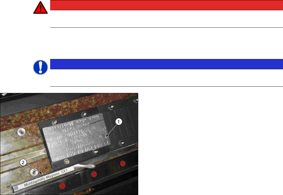
Fig.27: Magnet with cover
1. Magnet with cover
2. Assembly gauge (Y magnet spacing)
► Use the assembly gauge to align the magnet
plate and fix the first magnets into place with four
screws of type M5x18 and a force of 6Nm.
► The second magnet is only fixed with three
screws. The bottom left screw is not needed!
► Fit the end position buffers. Use the long buffers for SX1 machines.
See also the "Gantry Modularity Assembly Instructions" [00196626-xx].
3 Fitting the Prepare Kit
3.7 Fitting the End Stop and Preparing the Prepare Kit Case
Assembly Instructions / Montageanleitung SIPLACE SX1/SX2
Prepare Kit 04/2017
70
3.7 Fitting the End Stop and Preparing the Prepare Kit Case
Parts, equipment and tools
●
1x plastic case [03081445-xx]
– 1x buffer stop [03073028-xx]
– 1x buffer stop with actuator [03079647-xx]
Installation
► Fit the bracket to the buffer stop (pre-fitted).
► The actuator is fitted to the bracket with two countersunk screws (pre-fitted).
► Equip the prepare kit case as follows:
NOTICE
The content of the prepare kit case differs depending on the machine type (SX1 or SX2).
The case for an SX1 prepared machine only contains the short buffer stops.
The SX2 case contains the long buffer stops, the trailing cable bracket, the heat-shrinkable
hose and the four plugs.
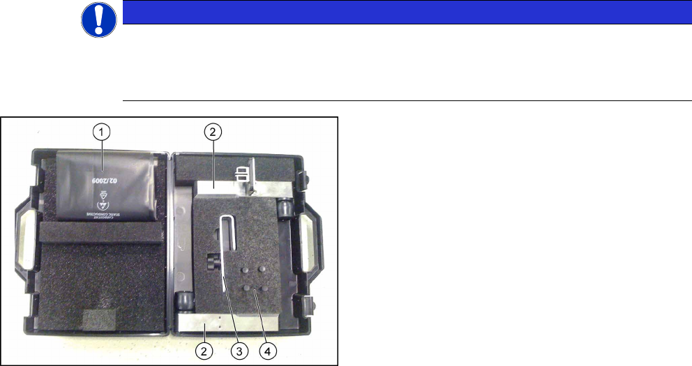
Fig.28: Prepared case
1. Heat-shrinkable hose
2. Buffer stops
3. Trailing cable bracket
4. 4x plugs
Assembly Instructions / Montageanleitung SIPLACE SX1/SX2
Prepare Kit 04/2017
3 Fitting the Prepare Kit
3.8 Final Work
71
3.8 Final Work
Side cover on infrastructure box
► Fit the inner side cover on the infrastructure box.
► Check once more that all cables have been run correctly and that the trailing cable is fixed in
the bracket.
NOTICE
Do not damage the cables
Make sure that the fans in the hood cover cannot damage any of the cables!
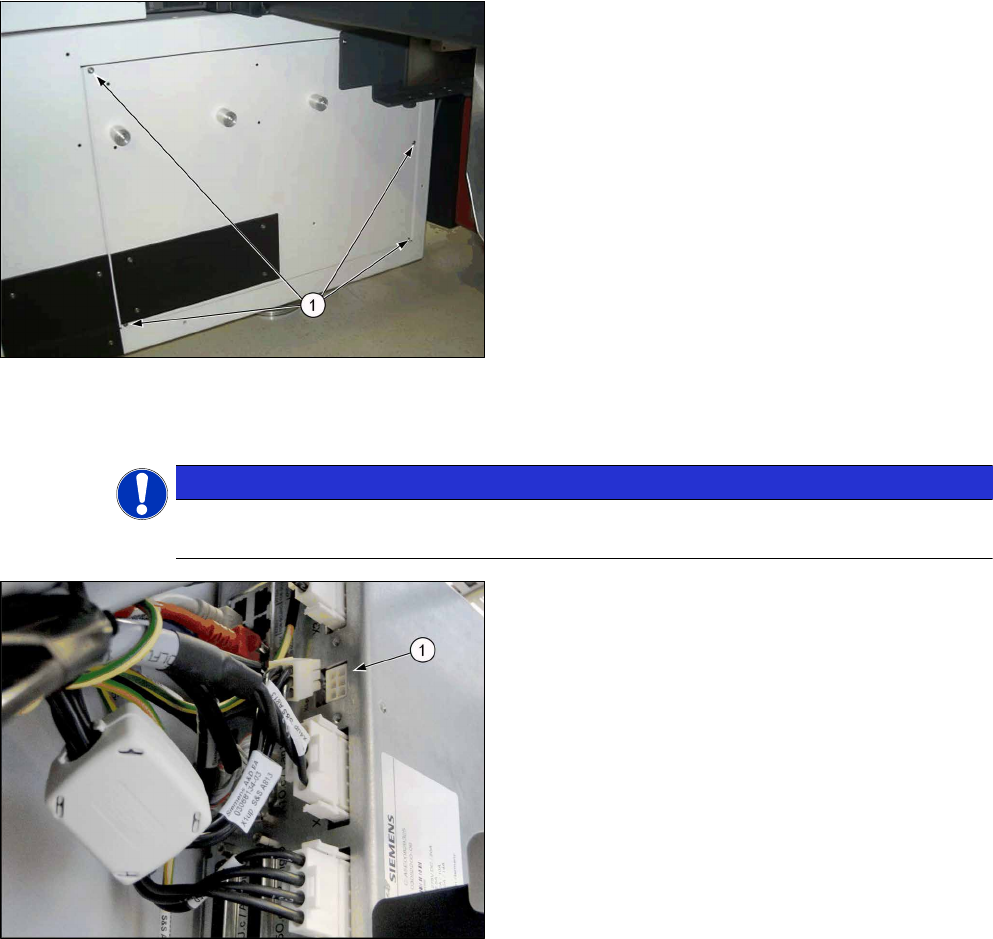
1. Unplug the cable [03068134-xx]
► To ensure a correct start-up of the machine,
please check that the GCU3 power cable has
been unplugged from the X1up connector.
► Attach the GCU label to the inside of the door, above the power supply of infrastructure box 3.
ð The installation is now complete.
Troubleshooting
Error Description:
●
The machine performs a reference run after each time the hoods have been opened.
Solution:
► Check pins 5 and 6 at X1 (PowerEnable and PowerFail) at the GCU.
► For more information, refer to the SIPLACE service.