00197182-04_AI_Prepare_Kit_SX12_de_en.pdf - 第60页
3 Fitting the Prepare Kit 3.3 Preparing and Fitting the GCU Assembly Instructions / Montageanleitung SIPLACE SX1/SX2 Prepare Kit 04/2017 60 Fig.10: GCU on carrier 1. GCU front side 2. Ground connection for GCU 3. Jumper…
Assembly Instructions / Montageanleitung SIPLACE SX1/SX2
Prepare Kit 04/2017
3 Fitting the Prepare Kit
3.3 Preparing and Fitting the GCU
59
3.3 Preparing and Fitting the GCU
Parts, equipment and tools
●
GCU carrier [03065813-xx]
– 2x hexagonal nuts M4 [03008166-xx]
– Ground M5 [03050528-xx]
– 3x socket-head screw M4x8 mm [03042551-xx]
●
Bracket assembly [03066100-xx]
●
Positioning control unit for gantry axes GCU [03052200-xx]
●
C-parts GCU carrier [03094644-xx]
– 2x hexagonal nuts M4 [03008166-xx]
– 5x socket-head screw M4x8 mm [03042551-xx]
– 2x serrated lock washer 4-FSt [03047857-xx]
– 1x contact disc 4 FSt [03047654-xx]
– 5x washers 4.3mm [00316894-xx]
Installation
► Check the jumper setting on the GCU. This must be as follows for the GCU 3:
Jumper Position
1 Left (OFF)
2 Right (ON)
3 Right (ON)
4 Left (OFF)
See also:
●
4.1.1 "GCU (Up To Machine No. Mxxxx)" [}73]
●
4.1.2 "MGCU (From Machine No. Nxxxx to Oxxxx)" [}74]
●
4.1.3 "MGCU - Full Mode (From Machine No. Pxxxx)" [}75]
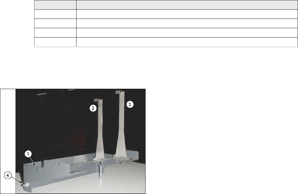
Fig.9: Carrier
1. Pre-drilled hole for threaded pin on GCU
2. Bracket for GCU 1/3, rear position
3. Bracket for GCU 1, front position
(not used for location 2)
4. Ground connection GCU carrier
3 Fitting the Prepare Kit
3.3 Preparing and Fitting the GCU
Assembly Instructions / Montageanleitung SIPLACE SX1/SX2
Prepare Kit 04/2017
60
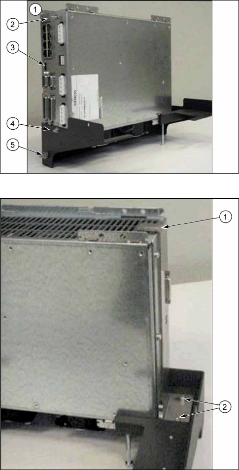
Fig.10: GCU on carrier
1. GCU front side
2. Ground connection for GCU
3. Jumper
4. Fixture for GCU threaded pin
5. Ground connection GCU carrier
Fig.11: Bracket
1. Bracket, hooked up to top of GCU
2. Bracket bottom fixture
► Place the GCU in its carrier. Make sure you position it correctly.
► The threaded pin on the front of the GCU is inserted through the pre-drilled hole on the carrier
and fixed into place with the serrated lock washer and the hexagonal nut (M4).
► The bracket is hooked up to the back of the GCU (at the top) and fixed into place at the bot-
tom of the support, using two washers and two socket-head screws (M4x8 mm).
► Fit the carrier and GCU on the left, above the Y magnets, using three washers and the three
socket-head screws M4x8 mm. (assembly position, see also location 1 GCU1/2)
► Fit the threaded pin for the GCU ground with a contact disc, a serrated lock washer and the
hexagonal nut M4. The ground wire from the cable [03068133-xx] will be connected to this
later on.
Assembly Instructions / Montageanleitung SIPLACE SX1/SX2
Prepare Kit 04/2017
3 Fitting the Prepare Kit
3.4 GCU cabling
61
3.4 GCU cabling
Parts, equipment and tools
●
Cable set for gantry 2 [03052290-xx]
– 1x cable Y1 motor gantry 2 [03055221-xx]
– 1x cable Y2 motor gantry 2 [03055223-xx]
– 1x cable sensor bus Y motor gantry 2 [03055226-xx]
– 1x cable RT-HCU bus gantry 2 [03055225-xx]
– 1x cable main axis voltage GCU 3 [03068133-xx]
– 1x cable auxiliary voltages GCU 3 [03068134-xx]
– 1x cable trailing cable interface 2 [03068135]
– 1x ground cable 1m length [03055212-xx] GCU carrier to ground surface
– 2x ground cable 1m length [03055213-xx] (see preparation for trailing cable interface)