00196626-06_AI_Portalmodularitaet_SX12_de_en.pdf - 第101页
Fitting the Gantry Note GCU Final Work Gantry Modularity Portalmodular ität 101 3.6.3 Note GCU Power cable GCU 3 [03068 134-xx] ► Please check the connection of the GCU3 power cab le with the co nnector X1up. (1) to ensu…
Fitting the Gantry
Final Work Stowing the Gantry Carrier and the Prepared Case
100 Gantry Modularity Portalmodularität
3.6 Final Work
3.6.1 Stowing the Gantry Carrier and the Prepared Case
Stowing the gantry carrier in the transportation crate
► Use the gantry lift to move the gantry carrier into the transportation crate.
► Fix the gantry carrier into place in the transportation crate, with the 4 fastening screws.
► Release the gantry carrier from the gantry lift and move the gantry lift to one side.
► Place the foam cover for the placement head in the transportation crate.
► Close the front and top cover on the transportation crate.
Placing assembly parts in the "Prepared" case
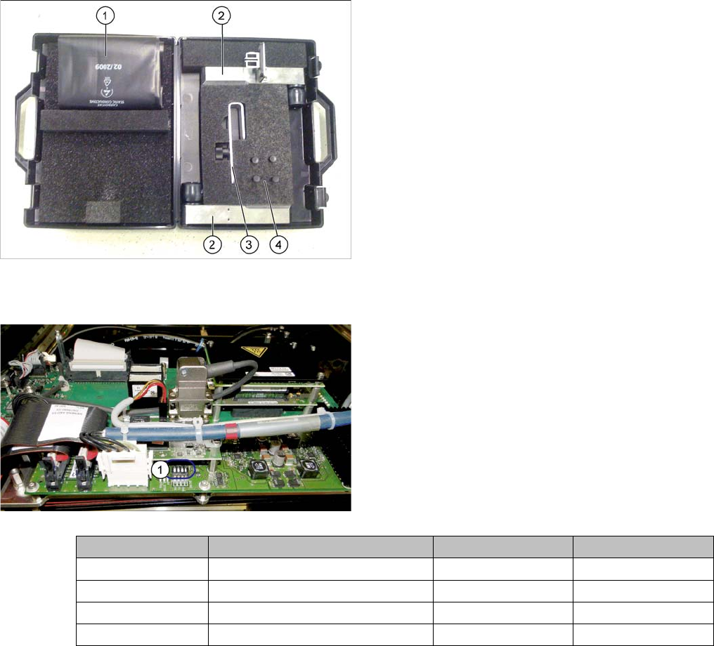
3.6.2 Checking the Gantry Coding
You have removed the following parts which you will
need to dismantle the gantry later on. Keep these parts in
the "Prepared" case.
▪ The long end position buffer
▪ A green lever as transportation lock for the gantry
▪ Two transportation locks for the placement head
▪ Black plastic foil for trailing cable
▪ Trailing cable holder with knurled head screw
► Check the DIP switch (1) for the gantry coding of the
locations on the head interface.
Switch Designation Gantry 1 Gantry 2
1 DC/DC OFF OFF
2FANOFFOFF
3P1OFFON
4P0OFFOFF
Fitting the Gantry
Note GCU Final Work
Gantry Modularity Portalmodularität 101
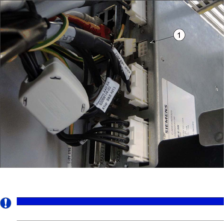
3.6.3 Note GCU
Power cable GCU 3 [03068134-xx]
► Please check the connection of the GCU3 power cable with the connector X1up. (1) to ensure a cor-
rect start-up of the machine.
NOTICE
Dismantling a Gantry
The connector X1up has to be disconnected from the GCU3, if the gantry is dismantled later on.
Fitting the Gantry
Final Work Checking the Camera Cable
102 Gantry Modularity Portalmodularität
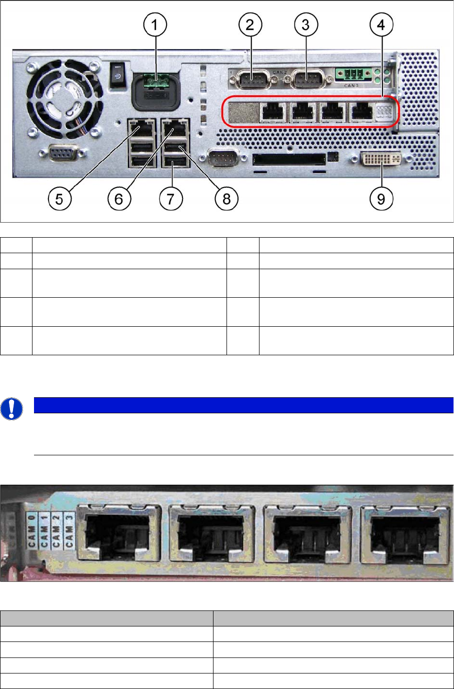
3.6.4 Checking the Camera Cable
► Check whether the camera cable is connected to the hotlink card on the box PC. Make sure that the
connections are correct. (See labelling on hotlink card).
Hotlink card [03032343-xx]
Hotlink card [03032343-xx]
(1) Power supply DC 24 V (2) CAN 1 on the CAN bus card
(3) CAN 2 on the CAN bus card (4) Hotlink card
(5) LAN 2 – connection to Vision computer
(optional second BoxPC)
(6) LAN 1 – connection to SIPLACE Pro
(connection to line hub)
(7) USB 0 – connection for keyboard/touch-
screen (connection to USB hub)
(8) USB 2 – connection for an external DVD
drive
(9) DVI/VGA monitor connection
(connection to video multiplexer)
NOTICE
Hotlink card:
Pay attention to the connections of the different hotlink cards, recognizable due to the sticker
(see the following explanation)!
Connection on the hotlink card Designation
CAM0 Head cameras gantry 1
CAM1 Head cameras gantry 2
CAM2 Stationary cameras gantry 1
CAM3 Stationary cameras gantry 2