00196626-06_AI_Portalmodularitaet_SX12_de_en.pdf - 第108页
Fitting the Gantry Final Wo rk Modifi cation s in SIPLAC E Pro 108 Gantry Modularity Portalmodularität 3.6.7 Modifications in SIPLACE Pro Station The SX mach ine type h as to be co nfigured in th e Station Edit or. At th…
Fitting the Gantry
Performing Calibration Final Work
Gantry Modularity Portalmodularität 107
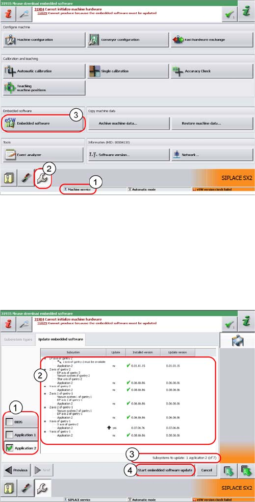
3.6.6.2 Firmware Download
► Select the Update machine.. button to check the whole machine and to perform an eSW download
for multiple subsystems.
► Select the Update subsystem... button to select and check a specific subsystem, in order to perform
an eSW download.
► Select theVersion Information... button in order to display all subsystem versions, Bios application 1/
2.
► The function Firmware Download can be performed
with the operator levels (1) Machine-Service or
SIPLACE-Service.
► Switch over to the service menu (2).
► Select the button Embedded Software (3).
1. Selection button, BIOS application 1/2
2. Shows the status of the individual subsystems.
3. Update information about the number of subsystems
which still have to be downloaded.
4. Starts the download.
Fitting the Gantry
Final Work Modifications in SIPLACE Pro
108 Gantry Modularity Portalmodularität
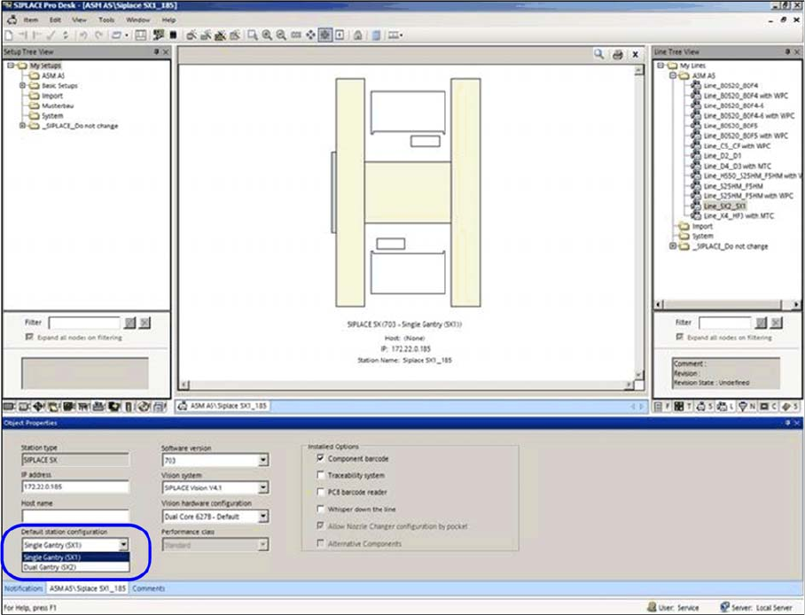
3.6.7 Modifications in SIPLACE Pro
Station
The SX machine type has to be configured in the Station Editor. At the standard station configuration
either Single gantry (SX1) or Double gantry (SX2) can be selected.
The new machine configurations are automatically used for new setups.
After a hardware change adequate modifications have to be made in SIPLACE Pro.
Station configuration setting Single gantry (SX1) or Double gantry (SX2)
Fitting the Gantry
Modifications in SIPLACE Pro Final Work
Gantry Modularity Portalmodularität 109
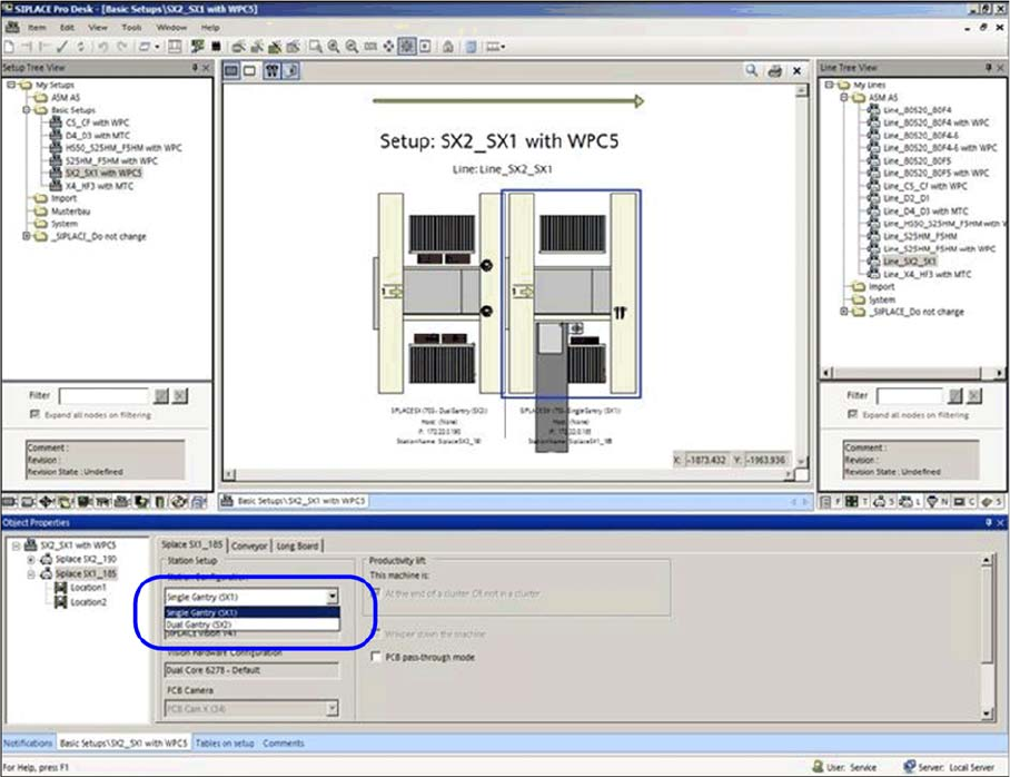
Setups
The new gantry configuration of the station configuration is used automatically when new setups are cre-
ated
If the existing Setups should be used in the future then each setup must be changed to match the gantry
configuration.
Modification of gantry configuration in the respective setup.
Location 2 can be configured afterwards.
The respective head, cameras, nozzles and tables at location 2 has to be edited.