00196626-06_AI_Portalmodularitaet_SX12_de_en.pdf - 第113页
Dismantling a Gantry Gantry Modularity Portalmodular ität 113 4 Dismantling a Gantry 1. Get the transportatio n crate with gantry carrie r and "Prepare d" case ready. – Dummy plugs for hoses – Black plastic foi…
Fitting the Gantry
Checklist Modifications in SIPLACE Pro
112 Gantry Modularity Portalmodularität
Dismantling a Gantry
Gantry Modularity Portalmodularität 113
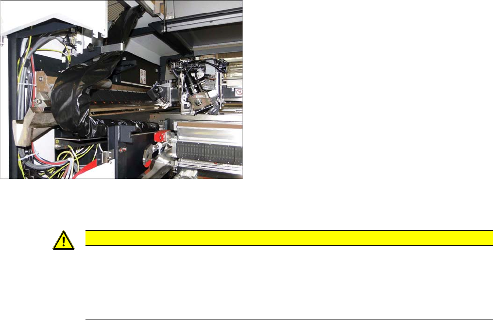
4 Dismantling a Gantry
1. Get the transportation crate with gantry carrier and "Prepared" case ready.
– Dummy plugs for hoses
– Black plastic foil for trailing cable
– Long end position buffer
– Trailing cable holder and knurled head screw
– Loose lever for transportation lock
2. Remove the gantry carrier from the transportation case with the gantry lift and lock into place.
3. Remove the keyboard and open the two side covers.
4. Push the gantry into a suitable working position in the machine.
5. Disconnect the trailing cable from the gantry interface of the X and Y axis (flat ribbon cable and hos-
es).
6. Close the 4 hoses on the trailing cable with the dummy plugs.
7. Dismantle the trailing cable fixture from the Y sensor module holder with the two hexagon spacer
bolts.
8. Pack the trailing cable with the black foil.
9. Fit the trailing cable holder and the trailing cable.
10. Move the placement head into the center of the gantry. This ensures that the load is distributed even-
ly.
11. Fit the two transportation locks for the placement head. The head must be in the center of the gantry.
12. Move the gantry lift with locked gantry carrier up to the docking unit of the machine.
13. Remove both end position buffers.
14. Using the docking hooks, hook the gantry carrier into the openings of the docking unit.
15. Push the gantry onto the gantry carrier and make sure that the tilt guard engages into place!
16. Lift the gantry lift with the gantry carrier and the gantry out of the docking unit and move it out of the
machine.
17. Attach the 3 transportation locks for the gantry to the gantry carrier! Only transport the gantry with
the gantry carrier when all transportation locks are in place! Do not move the gantry with the gantry
carrier over long distances. The transportation crate must be in the immediate vicinity of the ma-
chine.
18. Open the transportation crate at the top and front. The 4 screws are secured with the chain at 4
points.
19. Lift the gantry with the gantry carrier into the crate and tighten the 4 screws.
20. Unlock the gantry carrier from the gantry lift and move the lift away.
21. Place the foam cover over the placement head and close the crate.
Dismantling a Gantry
Final work on the machine
114 Gantry Modularity Portalmodularität
4.1 Final work on the machine
► At location 2 only: fit the long end position buffer if the gantry has been removed. Use a torque
wrench to tighten to 14 Nm. Take a look at the buffer monitoring function! The safety switch for for
the buffer monitoring function must engage in the Schmersal switch.
► Fit the keyboard and close the two side doors again.
► Calibrate (see below).
► Fit the trailing cable to the holder next to the GCU.
CAUTION
Check, stationary camera, nozzle changer
► Check whether gantry 1 can move to location 2 unhindered and whether it can also reach
the table pickup position.
► In certain configurations, you need to dismantle the stationary camera and the second noz-
zle changer row and then move the table from the outer to the inner position.