00196626-06_AI_Portalmodularitaet_SX12_de_en.pdf - 第95页
Fitting the Gantry Transportation Locks and Tilt Guard Installing the Gantry Gantry Modularity Portalmodular ität 95 Remove the tilt guard and move in the gantry The docking hooks are hooked into place on the left (1) an…
Fitting the Gantry
Installing the Gantry Transportation Locks and Tilt Guard
94 Gantry Modularity Portalmodularität
3.4 Installing the Gantry
Hooking the gantry carrier into place on the machine
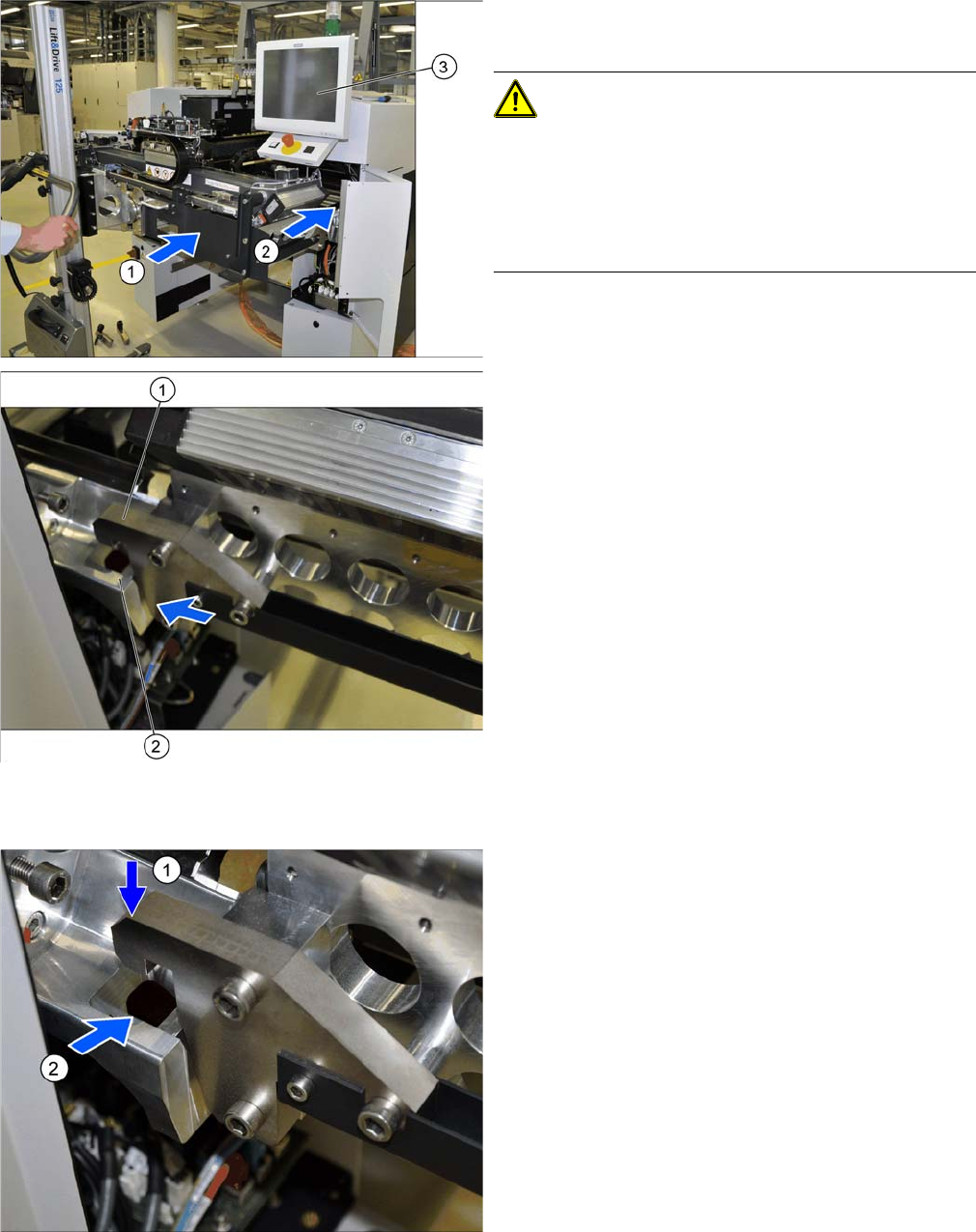
► (1) Use the gantry lift to move the gantry in front of the
machine location.
CAUTION!
Move the gantry carefully
Make sure that you do not damage the monitor (3).
Make sure that you do not hit the gantry anywhere and do
not move it too far into the machine (2). Always check the
right and left sides.
1. Docking hook on the gantry carrier
2. Docking unit on the machine linear guides
► Move the gantry forwards so that the gantry carrier
docking hooks (1) are in front of the machine docking
unit (2).
► Always check the right and left sides.
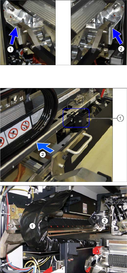
► Lift the gantry so that the gantry carrier docking hooks
(1) are above the machine docking unit (2).
► Carefully lower the gantry so that the two docking
hooks (1) slide reliably into the openings in the dock-
ing unit (2).
► Always check the right and left sides.
Fitting the Gantry
Transportation Locks and Tilt Guard Installing the Gantry
Gantry Modularity Portalmodularität 95
Remove the tilt guard and move in the gantry
The docking hooks are hooked into place on the left (1)
and right (2) sides.
The gantry carrier with the gantry is now fixed reliably
onto the machine.
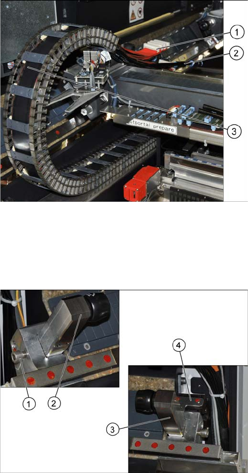
► Open the tilt guard (1).
► Push the gantry (2) into the machine so that both
sides of the gantry rest on the two linear guides.
► Move the gantry lift with the gantry carrier out of the
location.
► Move the gantry (2) into the machine so that the trail-
ing cable (1) can be pulled underneath, through the
gantry.
Fitting the Gantry
Installing the Gantry Fitting the Short End Position Buffer
96 Gantry Modularity Portalmodularität
3.4.1 Fitting the Short End Position Buffer
The short end position buffer must be fitted in SIPLACE SX machines with two gantries. This buffer
needs to be removed and replaced with the long end position buffer in SIPLACE SX machines with one
gantry at location 1.
► Carefully place the flat ribbon cable (1) and the pneu-
matic connections (2) over the gantry.
► Remove the black plastic foil. A cable tie fixes the
black plastic foil to the trailing cable (1).
► Fit the end position buffer (2) to the left side.
► Fit the end position buffer (3) to the right side. The
safety switch (4) for the buffer monitoring function
must engage in the Schmersal switch.
► Tighten the fastening screws (1) for both buffers.