00196626-06_AI_Portalmodularitaet_SX12_de_en.pdf - 第103页
Fitting the Gantry Fitting the Nozzle Changer and Options Final Work Gantry Modularity Portalmodular ität 103 Hotlink card [03052135-xx] Hotlink card [03052135 -xx] 3.6.5 Fitting the Nozzle Changer and Options Installing…
Fitting the Gantry
Final Work Checking the Camera Cable
102 Gantry Modularity Portalmodularität
3.6.4 Checking the Camera Cable
► Check whether the camera cable is connected to the hotlink card on the box PC. Make sure that the
connections are correct. (See labelling on hotlink card).
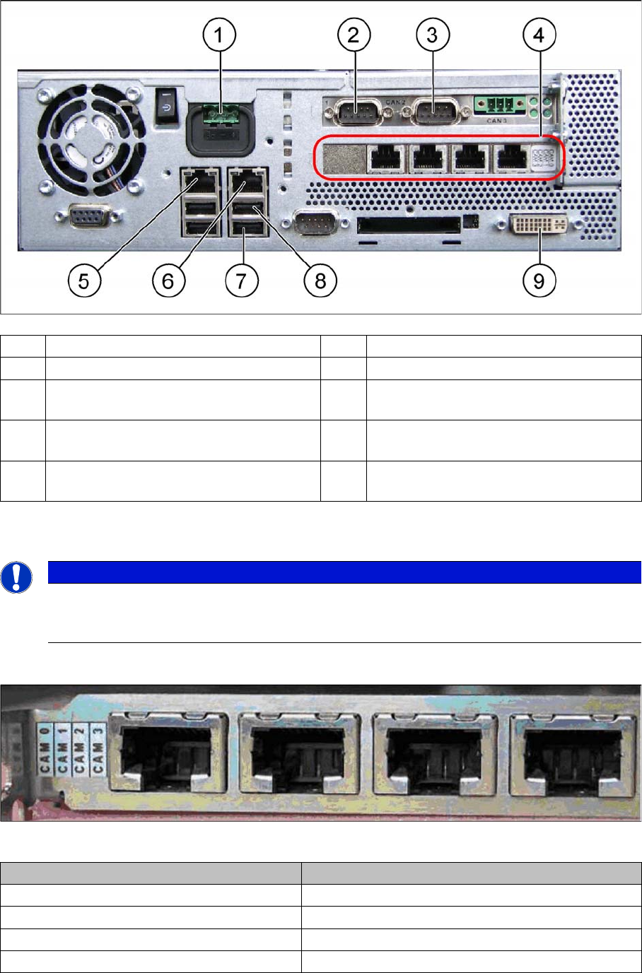
Hotlink card [03032343-xx]
Hotlink card [03032343-xx]
(1) Power supply DC 24 V (2) CAN 1 on the CAN bus card
(3) CAN 2 on the CAN bus card (4) Hotlink card
(5) LAN 2 – connection to Vision computer
(optional second BoxPC)
(6) LAN 1 – connection to SIPLACE Pro
(connection to line hub)
(7) USB 0 – connection for keyboard/touch-
screen (connection to USB hub)
(8) USB 2 – connection for an external DVD
drive
(9) DVI/VGA monitor connection
(connection to video multiplexer)
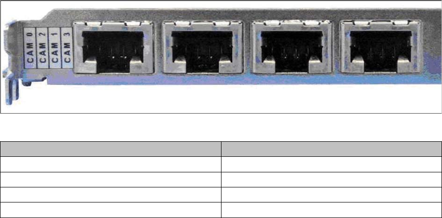
NOTICE
Hotlink card:
Pay attention to the connections of the different hotlink cards, recognizable due to the sticker
(see the following explanation)!
Connection on the hotlink card Designation
CAM0 Head cameras gantry 1
CAM1 Head cameras gantry 2
CAM2 Stationary cameras gantry 1
CAM3 Stationary cameras gantry 2
Fitting the Gantry
Fitting the Nozzle Changer and Options Final Work
Gantry Modularity Portalmodularität 103
Hotlink card [03052135-xx]
Hotlink card [03052135-xx]
3.6.5 Fitting the Nozzle Changer and Options
Installing the required nozzle changer (head-related)
► See also the "Nozzle Changer Assembly Guide for SIPLACE SX series German/English"
[00196578-xx].
Fitting the stationary cameras (optional)
► See also the "Stationary Camera Type 33 Assembly Guide German/English" [00196608-xx] and the
"Stationary Camera Type 25 Assembly Guide German/English" [0094554-xx].
Fitting the component reject bin query (optional)
► See also the "Reject Bin Query Assembly Guide for SIPLACE SX1/SX2 German/English"
[00196615-xx].
Taking into account the component trolley docking unit inner/outer
► See also the "SIPLACE SX1/SX2 Service Manual" [German: 00196496-xx] [English: 00196497-xx]
Connection on the hotlink card Designation
CAM0 Head cameras gantry 1
CAM2 Stationary cameras gantry 1
CAM1 Head cameras gantry 2
CAM3 Stationary cameras gantry 2
Fitting the Gantry
Final Work Performing Calibration
104 Gantry Modularity Portalmodularität
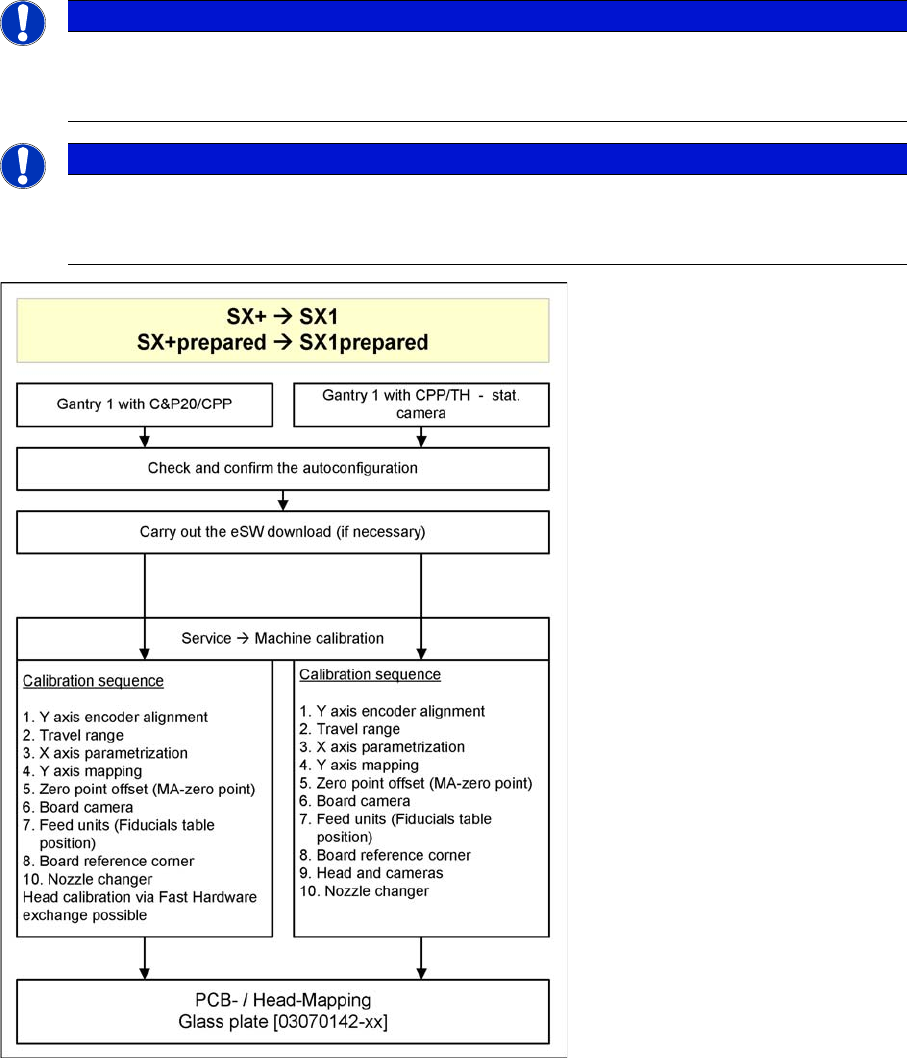
3.6.6 Performing Calibration
Overview
The SW704 divides the mapping data and then merges them during the gantry upgrade. In most cases
this means that only a brief calibration procedure needs to be performed (see Fast Hardware Exchange
and flow diagram).
If gantry 1 is fitted, you need to perform PCB/component mapping with the glass plate, irrespective of
the head configuration (gantry 1 is the master gantry).
NOTICE
TH gantry at location 2
If there is a TH gantry at location 2 (gantry 2), the PCB mapping data must be present. Com-
ponent mapping can then be performed using the aluminum plate.
NOTICE
Long Board Option
If a gantry is installed on a machine with Long Board Option (LBO), this gantry has to be
mapped with the mapping with LBO button.