00196626-06_AI_Portalmodularitaet_SX12_de_en.pdf - 第99页
Fitting the Gantry Fitting the Short End Position Buffer C onnecting the Trailing Cable Gantry Modularity Portalmodular ität 99 Connections established This diagram shows the preci sely run and c orrectly ar - ranged con…
Fitting the Gantry
Connecting the Trailing Cable Fitting the Short End Position Buffer
98 Gantry Modularity Portalmodularität
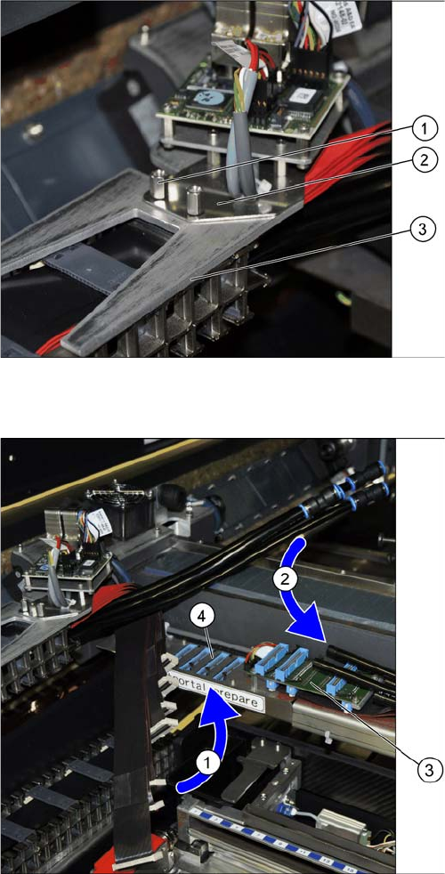
Trailing cable holder - overview
Restore the electrical and pneumatic connections
1. Two hexagon spacer bolts M4 x 10 mm.
2. Gantry board holder
3. Trailing cable holder
► Loosen the two hexagon spacer bolts M4 x 10 mm on
the trailing cable holder.
► Hold the trailing cable holder from below, on the gan-
try board holder.
► Screw the two hexagon spacer bolts from above, into
the trailing cable holder.
► Secure the two hexagon spacer bolts with Loctite
241.
► First connect the 7 flat ribbon cables (1) to the boards
for the gantry interface of the X axis (3) and the gantry
interface of the Y axis (4). The sequence depends on
the different cable lengths. Work your way from back
to front.
► Remove the dummy plugs from the pneumatic hose
couplings.
► Connect the four pneumatic connections for the trail-
ing cable to the gantry connections (2). The se-
quence depends on the different hose lengths..
Fitting the Gantry
Fitting the Short End Position Buffer Connecting the Trailing Cable
Gantry Modularity Portalmodularität 99
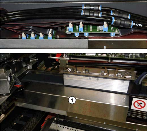
Connections established
This diagram shows the precisely run and correctly ar-
ranged connections.
► Fit the cover (1) over the gantry interface.
Fitting the Gantry
Final Work Stowing the Gantry Carrier and the Prepared Case
100 Gantry Modularity Portalmodularität
3.6 Final Work
3.6.1 Stowing the Gantry Carrier and the Prepared Case
Stowing the gantry carrier in the transportation crate
► Use the gantry lift to move the gantry carrier into the transportation crate.
► Fix the gantry carrier into place in the transportation crate, with the 4 fastening screws.
► Release the gantry carrier from the gantry lift and move the gantry lift to one side.
► Place the foam cover for the placement head in the transportation crate.
► Close the front and top cover on the transportation crate.
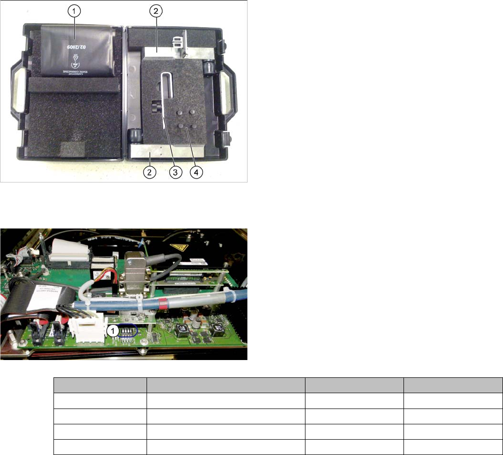
Placing assembly parts in the "Prepared" case
3.6.2 Checking the Gantry Coding
You have removed the following parts which you will
need to dismantle the gantry later on. Keep these parts in
the "Prepared" case.
▪ The long end position buffer
▪ A green lever as transportation lock for the gantry
▪ Two transportation locks for the placement head
▪ Black plastic foil for trailing cable
▪ Trailing cable holder with knurled head screw
► Check the DIP switch (1) for the gantry coding of the
locations on the head interface.
Switch Designation Gantry 1 Gantry 2
1 DC/DC OFF OFF
2FANOFFOFF
3P1OFFON
4P0OFFOFF