00198375-02_UM_OnBoardPCB-Inspection-R18-1_DE_EN.pdf - 第41页
2 What is Onboard PCB Inspection? 2.1 Customer Benefits User Manual / Bedienungsanleitung Onboard PCB Inspection 06/2018 41 2 What is Onboard PCB Inspection? During placement of printed circuit boards with components, On…
1 Introduction
1.1 General
40 User Manual / Bedienungsanleitung Onboard PCB Inspection 06/2018
1.1 General
1.1.1 Symbols / Notes
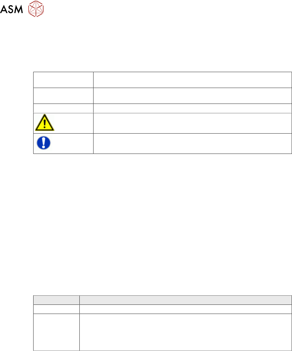
Different symbols and notes have been used to make it easier to read and understand this docu-
ment.
Words in bold/italic
print
These refer to dialogs, dialog fields, menu items, and commands.
Step ... Includes all actions to do with a particular dialog. A dialog may be com-
posed of several actions (→).
► Requires an action (e.g. mouse click, open file)
Indicates a warning. The information is essential for successful working.
Explanatory information.
1.1.2 ASM on the World Wide Web
Log in to our homepage at http://www.asm-smt.com.
► You can choose between the German and English versions.
The different sections contain information about our products, services and contact persons.
In addition, registered customers can also access the SIPLACE User Group. Here you can call up
special information about our placement systems, e.g.
●
Technical documentation,
●
Technical information,
●
spare parts lists etc.
Registration for the user group is very simple:
► Click the Register link.
► Fill in the registration form and send it off to us.
Soon afterwards, you will receive your access authorization with USER ID and password.
1.1.3 Release History
Edition Changes
09/2017 First edition
06/2018
●
Formal adjustments
●
Improvements and supplements
●
System requirements
●
New teaching views and parameters
2 What is Onboard PCB Inspection?
2.1 Customer Benefits
User Manual / Bedienungsanleitung Onboard PCB Inspection 06/2018 41
2 What is Onboard PCB Inspection?
During placement of printed circuit boards with components, Onboard PCB Inspection is used to in-
spect critical areas while the board is still in the placement machine.
The main use case for Onboard PCB Inspection is the placement of BGA components or shields.
The inspection is most beneficial for BGA components or shields, however, it can be used for all
component types.
If smaller components are positioned under these BGAs or a shield, an AOI system behind the
placement machine can only detect or repair errors that were made during the placement of the
small components with great effort or not at all.
The inspection is performed with the PCB camera which is already in the placement machine and
with which the fiducials are measured or with which barcodes on the board are read. No additional
hardware needs to be installed.
The inspection is a 3D procedure in which height data is compared. The height profiles are calcu-
lated using repeated capturing of images with special illumination.
The measurement is made by comparing images of a correctly placed board with those of the
board currently being placed. If any differences are found, the machine will stop. The differences
are classified, for example, as a missing component or an additional component. This is visualized
for the operator at the monitor of the station. Based on the images, the operator then decides
whether this is a real error or whether placement can continue.
The same method is used to determine whether the solder volume and solder paste height in se-
lected areas of an unplaced board match that of a correctly placed board.
2.1 Customer Benefits
●
Low dpm rate. The inspections are performed inside the SIPLACE placement machine and
without the need for any additional device.
●
Faster recognition of errors
●
Less subsequent reworking
●
Lower investment, if only certain areas on a board need to be inspected.
2.2 System Requirements
●
SIPLACE Pro version 15.1 or higher
●
Station software version 711.1 or higher
●
Machine licence:
– Item number: 00117262-01
●
SIPLACE Vision 5.5 or higher
●
All SIPLACE SX with PCB camera type 34 Q
– SIPLACE SX with hotlink cameras need to be converted to type 34 Q (item no.:
03075363-02).
●
All SIPLACE SX with high gantry, VHF head and PCB camera of type 34 HU
●
SIPLACE TX or X-Series S with PCB camera type 34 G (GigE)
●
In machines with high force head, only use with PCB camera type 34 H (may need to be retro-
fitted)
NOTICE
SIPLACE X-Series S from serial number Hxxxx onwards
All SIPLACE X-Series S from serial number Hxxxx or higher are already fitted with GigE.
2 What is Onboard PCB Inspection?
2.3 The Inspection Methods
42 User Manual / Bedienungsanleitung Onboard PCB Inspection 06/2018
2.3 The Inspection Methods
2.3.1 Solder Paste Inspection (SPI)
This inspection method checks the quality of the solder paste which has been applied. The solder
paste in the component placement area is inspected before placement.
●
Both the solder volume and the average solder height are inspected.
●
Clearly detectable solder bridges are recognized.
●
The inspection is performed in the first machine of the line.
2.3.2 Before Placement Inspection (BPI)
This inspection method checks whether the previously placed components are missing at the
placement position or whether lost components are present there. This is particularly useful for
BGA, LGA or QFP components and also for shields.
Application cases for component types
●
The main use case is to check if all components are present. Whether components are placed
with an offset, is only detected for large offsets (however, this inspection method is no meas-
uring tool for checking the placement accuracy).
●
Before a BGA, an LGA or QFP component is placed, an inspection can be performed to make
sure that no other component or foreign body is on or next to the solder deposits. This en-
sures that the BGA balls are placed directly onto the solder pads.
●
Before a shield is placed over components, an inspection is performed to make sure that
these previously placed components are already present in the correct places (under the
shield).
2.3.3 After Placement Inspection (API)
This inspection method checks whether the component has been correctly placed.
●
Components which have already been placed will be inspected to see if they have been cor-
rectly placed in the right position.
2.4 Prerequisites and Restrictions
2.4.1 General Notes
●
In exceptional cases, you may need to repeat the teaching process, if the appearance of the
placed boards, the solder paste pressure etc. has changed significantly from the original
teaching result. The better the teached reference image is, the better will be the result later
on.
●
Pseudo errors could occur as an exception. This is mainly the case if shadowing effects occur
i.e. if components are placed too close to each other or if relatively high components have
been placed already.
NOTICE
Recognition performance depends on the actual use case
The recognition performance depends on the actual use case. That means you always
have to check and decide for the actual case how good the procedure works. In unfavor-
able cases, an increased "error alarm" rate or some not recognized "lost components" can
be expected. A 100% security is not guaranteed.
●
The placement positions to be inspected must have an angle which is a multiple of 90°.