00198375-02_UM_OnBoardPCB-Inspection-R18-1_DE_EN.pdf - 第55页
4 Teaching Inspection Areas at the Station 4.3 Teaching with Before Placement Inspection (BPI) User Manual / Bedienungsanleitung Onboard PCB Inspection 06/2018 55 The operator is warned if the detected solder heights dif…
4 Teaching Inspection Areas at the Station
4.2 Teaching Solder Paste Inspection (SPI)
54 User Manual / Bedienungsanleitung Onboard PCB Inspection 06/2018
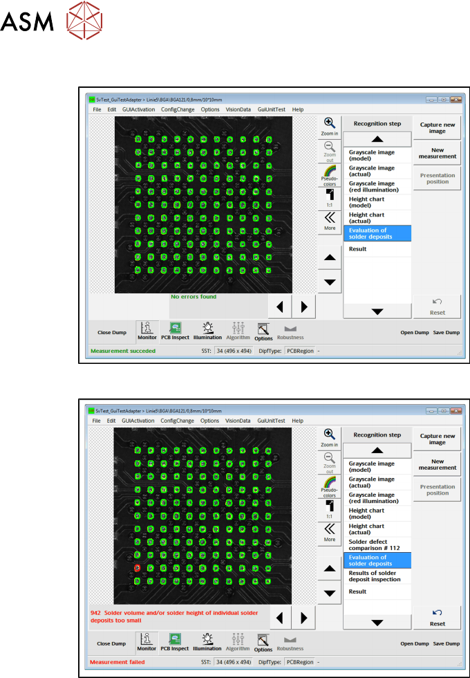
Successful
With errors
If defects are already detected here, teach again with a better sample PCB.
In the example, a solder pad is marked red for defective. The respective error message with a solu-
tion will be shown.
In example no. 942: Solder volume and/or solder height of individual deposits too small.
4.2.3.2 Average Heights of Solder Deposits
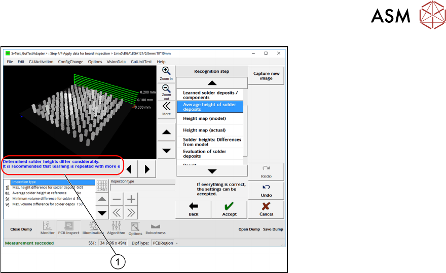
The average height for each detected solder deposit is shown in a 3D view.
► Go to Recognition step and select Average height of solder deposits.
4 Teaching Inspection Areas at the Station
4.3 Teaching with Before Placement Inspection (BPI)
User Manual / Bedienungsanleitung Onboard PCB Inspection 06/2018 55
The operator is warned if the detected solder heights differ greatly. Consider this message (1).
Nevertheless, you can start the inspection.
Tips and tricks
●
Re-teach with a better solder paste pressure.
4.3 Teaching with Before Placement Inspection (BPI)
Two things are inspected:
Lost components
●
Is there a (previously lost) component in the inspection area which does not belong there?
– This check covers the entire inspection area.
Components already placed
●
Have all components been correctly placed?
– The aim of teaching is to learn where already placed components are located. Only these
can be inspected later on.
– A typical application case is to check whether all the components in this area have been
placed before another component (e.g. shield) is placed above them.
4 Teaching Inspection Areas at the Station
4.3 Teaching with Before Placement Inspection (BPI)
56 User Manual / Bedienungsanleitung Onboard PCB Inspection 06/2018
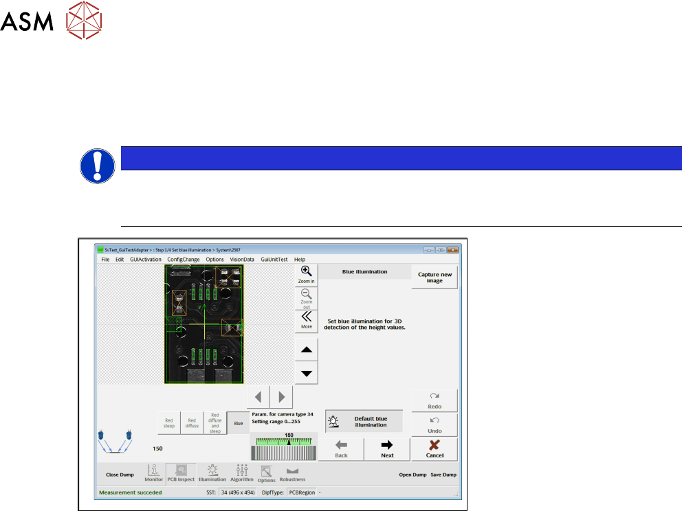
4.3.1 Setting the Illumination.
The placement positions in the teaching area must appear bright enough. If the lighting is too dark,
a hint is displayed at the end of the Teaching wizard. The components to be inspected and their
leads (if visible) need to have a sufficiently high contrast.
NOTICE
Blue lighting
Only the "blue" lighting is available for calculating the 3D information during Before Place-
ment Inspection (BPI).
●
Area with green border = part of the component description which is to be inspected
●
Area with orange border = the area or areas which are to be taught
●
Areas with yellow border = inspection area
●
Crossed out areas with yellow border = exclusion areas
●
For further information please refer also to the Online Help.
► Click on the Next button.
4.3.2 Setting the Teaching Area
The defined teaching areas can be selected at Teaching areas.
In these teaching areas, already placed components are searched for. All components found in
these areas are included in the model and will be checked for presence during the inspection. The
height profile (that is used to recognize lost components) is teached in the whole inspection area
(except for exclusion areas) i.e. lost components are not only found in the teaching areas.