00197043-04_VD_706_1_SP2_705_05_SP2_DE_EN.pdf - 第34页
Station S oftware 70 6. 1 SP 2 /705.05 SP 2 / Vers ion De scription Ausgabe 07/2013 E dition 34 Changing th e pic k - up pos ition will ha ve the foll owing cons equences: – The change d setting is transm itted to the fe…
Station Software 706.1 SP2/705.05 SP2 / Version Description Ausgabe 07/2013 Edition
33
6.11.8 Grafical Display of the Feeder Pick-up Position
Compatible mode: Complete
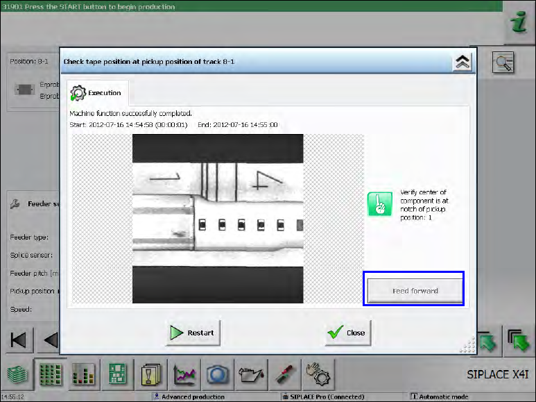
In the Details view of a feeder, a dialog can be opened via the Check tape position at pickup
position … button in which the camera image of the pick-up position with all pick-up position
markings (notches) on the feeder is displayed.
Figure 5-17: Details view of a feeder
Fine Adjustment of the Pitch at the Feeder
With the Feed forward button the smallest possible pitch can be set at the feeder. This concerns
the control of the feeder hardware only and has no other effect.
The purpose of this function is to position the feeder so that the tape pocket is possibly centered to
the recommended pick-up position / visible feeder notch.
The pick-up position can be set on the GUI for the following (tape) feeders:
– 4mm - 104mm X-feeders
For feeder types < 12mm, the current pitch in the feeder has to be set to > 4mm to achieve the
same functionality as on the operator panel of the feeder and to avoid incorrect settings for
smaller pitches.
– 12/16mm X Smart Feeder
Dependent of the current activity level, the feeder parameter can be changed in the lower area in
the Details view of a feeder.
Station Software 706.1 SP2/705.05 SP2 / Version Description Ausgabe 07/2013 Edition
34
Changing the pick-up position will have the following consequences:
– The changed setting is transmitted to the feeder that then presents the component at the new
defined position. To see the changed position, the operator has to restart the Check tape
position at pickup position dialog.
– If uploading is allowed, the changed pick-up position settings are immediately uploaded to
SIPLACE Pro into the local setup data.
After the feeder has been stepped with the Feed forward button, a new camera image of the pick-
up position will be automatically displayed. If necessary, the pick-up position has to be re-taught in
the Position correction dialog.
6.11.9 Tape Pocket Detection of Component Shape 0603
Compatible mode: Complete
The tape pockets of the 0603 component shape have been integrated in the default workflow of the
tape pocket detection. In connection with this change, the behavior in error cases has been
modified, too. After a pocket detection error has occurred, the software still tries to pick up the
component. If the component cannot be picked up, the machine stops with a vacuum error.
Additionally, the Check and teach feeder pocket shapes button is highlighted in red. If this button
is selected, a dialog is opened in which the tape pocket detection can be performed manually or be
skipped.
Station Software 706.1 SP2/705.05 SP2 / Version Description Ausgabe 07/2013 Edition
35
6.12 Fault-tolerant Operation of Twin Head
Compatible mode: Complete
Until now, the entire machine could not produce anymore if one Twin Head segment failed,
because no reference run could be performed for the concerned segment after machine start.
Usually, this caused a complete line downtime in the production.
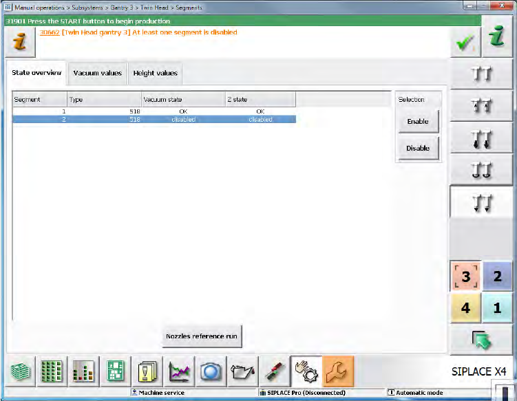
As of this station software version it is possible to deactivate the concerned Twin Head segment or
remove it from the configuration via the software.
With the Deactivate Segment option, the segment is not used during placement. However,
communication via CAN bus is possible and single actions can be performed with the segment,
e.g. securing the z-axis. This option corresponds to the method with which segments of the CPP
and C&P20 placement heads are deactivated and can be set during running operation under
Manual operations on the Machine service activity level.
Figure 5-18: Manual operations – deactivating segment
If both segments are deactivated but placement content is defined for the Twin Head, the machine
stops when the board enters and the Cannot continue production error message will be
displayed.