00197043-04_VD_706_1_SP2_705_05_SP2_DE_EN.pdf - 第36页
Station S oftware 70 6. 1 SP 2 /705.05 SP 2 / Vers ion De scription Ausgabe 07/2013 E dition 36 W ith the Remove Segment from configura ton optio n the segm ent is disc onnected f rom CAN bus and power s upply and no com…
Station Software 706.1 SP2/705.05 SP2 / Version Description Ausgabe 07/2013 Edition
35
6.12 Fault-tolerant Operation of Twin Head
Compatible mode: Complete
Until now, the entire machine could not produce anymore if one Twin Head segment failed,
because no reference run could be performed for the concerned segment after machine start.
Usually, this caused a complete line downtime in the production.
As of this station software version it is possible to deactivate the concerned Twin Head segment or
remove it from the configuration via the software.
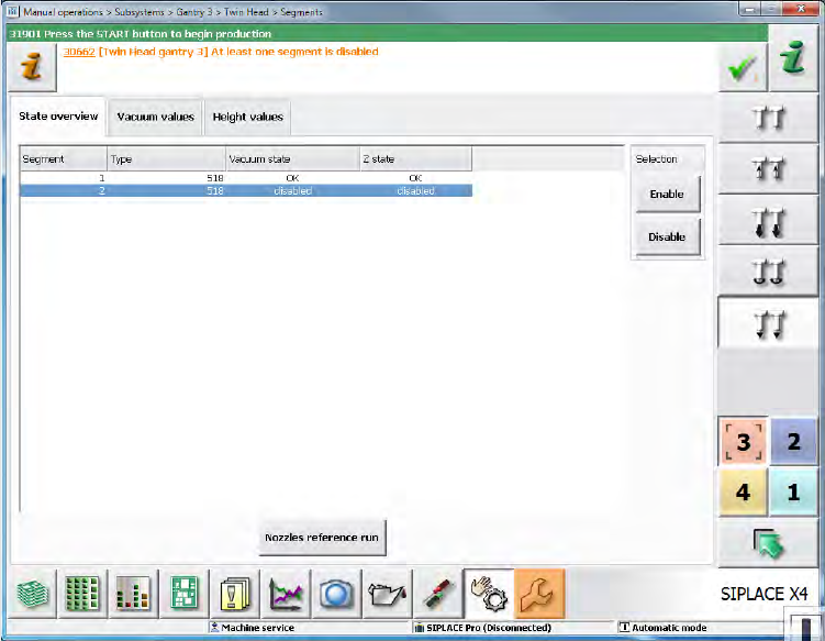
With the Deactivate Segment option, the segment is not used during placement. However,
communication via CAN bus is possible and single actions can be performed with the segment,
e.g. securing the z-axis. This option corresponds to the method with which segments of the CPP
and C&P20 placement heads are deactivated and can be set during running operation under
Manual operations on the Machine service activity level.
Figure 5-18: Manual operations – deactivating segment
If both segments are deactivated but placement content is defined for the Twin Head, the machine
stops when the board enters and the Cannot continue production error message will be
displayed.
Station Software 706.1 SP2/705.05 SP2 / Version Description Ausgabe 07/2013 Edition
36
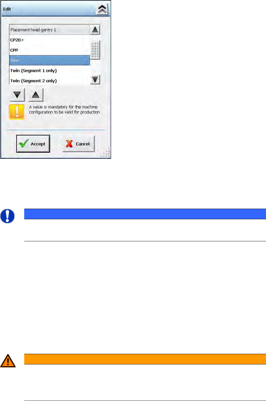
With the Remove Segment from configuraton option the segment is disconnected from CAN bus
and power supply and no communication is possible. This option can be selected in the Auto
Configuration under Service – Machine configuration on the Machine service activity level.
Figure 5-19: Machine configuration – Removing segment from configuration
As an additional option to Twin, it is possible to select either Twin (Segment 1 only) or Twin
(Segment 2 only).
The calibration steps are performed for the active segment only.
NOTICE
Head Calibration and Head Mapping
The head calibration and head mapping are only possible if Segment 1 is active!
Download of the embedded software is not provided for a segment that has been removed from the
configuration.
If Segment 1 has been deactivated or removed from the configuration, e.g. some single placement
positions might not be reachable because of the limited traveling range of Segment 2. In this case,
the machine stops with a corresponding error message and the board cannot be finished.
However, the placement position or the feeder can be omitted as usual.
If the head option in the Auto Configuration differs from the configured head option (Twin, Twin
(Segment 1 only) or Twin (Segment 2 only)), a corresponding message is displayed. The
inconsistency between the last and the current configuration is displayed in the Machine
configuration.
After the Twin Head configuration has been changed, the station software is rebooted
automatically.
WARNING
Do not dismantle a segment that is defect or has been removed from the
configuration!
A segment that is defect or has been removed from the configuration must not be
dismantled, as this might have negative effects on the gantry dynamics.
Station Software 706.1 SP2/705.05 SP2 / Version Description Ausgabe 07/2013 Edition
37
6.13 Error Message "Narrow edges on the encoder's track signals"
Compatible mode: Complete
The 30463 Encoder error: Narrow edges on the encoder's track signals error
message for placement machines with H-gantries (SX1/SX2 and DX1/DX2) has been modified so
that the error can be rapidly found.
The fixed bearing or floating bearing sides and the gantry number are additionally displayed in the
error message.
6.14 Automatic Backspacing to Lower Activity Level
Compatible mode: Complete
If the GUI stands in the Production view and no entries are made within a preset time, the software
automatically switches into the Basic production activity level. This is performed regardless of
which activity level was active before.
The backspacing and the time interval can be modified under Settings – GUI settings. Default: the
function is enabled.
6.15 SIPLACE LED Pairing
Compatible mode: Complete
SIPLACE LED Pairing supports the programming process when LEDs are used in electronic
assemblies.
In the *.LRX format the brightness class is added to the component name (in brackets) and usually
consists of 2 characters and in rare cases of 6 characters. The *.LRX2 fomat does not contain any
brightness class suffixes. Instead of that, a real component with an item number of its own is used
for each brightness class.
The brightness class / brightness class specific components are displayed in the Setup and Filling
level views on the GUI of the station software.