User-Manual-NeoDen9-PNP-machine.pdf - 第42页
42 Zhejiang Neoden T echnol ogy Co., Ltd 9.3 Ba sic Config uration Fig: Ba sic Con figuration Default Wor king Speed: th is is a dopted by the p lacement spee d in the moun ting interface Mark Camera Brightnes s and IC C…
41
Zhejiang Neoden Technology Co., Ltd
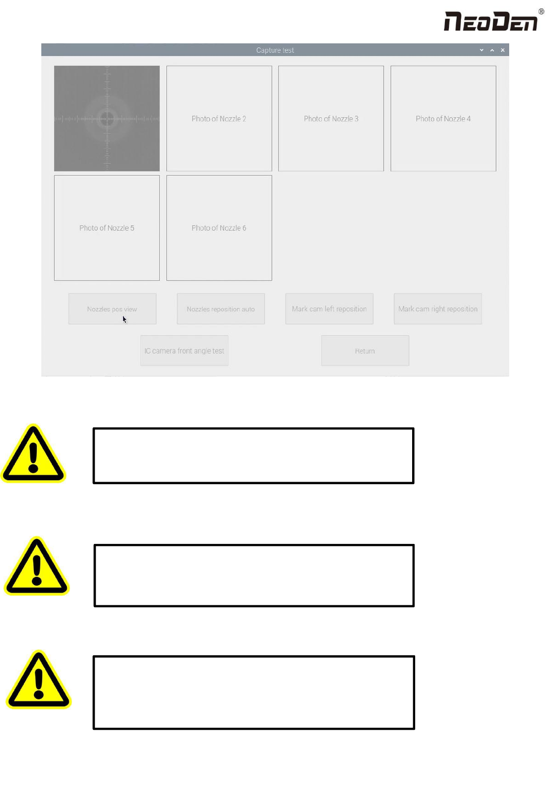
Fig.Auto Calibration Interface
8. XY Linear Encoder Initialize
9. Mounting Head Linear Encoder Initialize
10. Nozzle Height Set Zero
Warning:This is only need to be done after nozzle height set zero.
Please do not change it without checking with NeoDen Team.
Warning:
This is only need to do after the Linear was reinstalled or
some mechanism changed. Please do not change it without checking
with NeoDen Team.
Warning: This is a must-do step after replaced the motors and belts
or re-tested. Otherwise the nozzles may crash down to break
somewhere. And also please do this step cautiously under the
instruction from NeoDen technical engineer to avoid unnecessary
damage to the machine.
42
Zhejiang Neoden Technology Co., Ltd
9.3 Basic Configuration
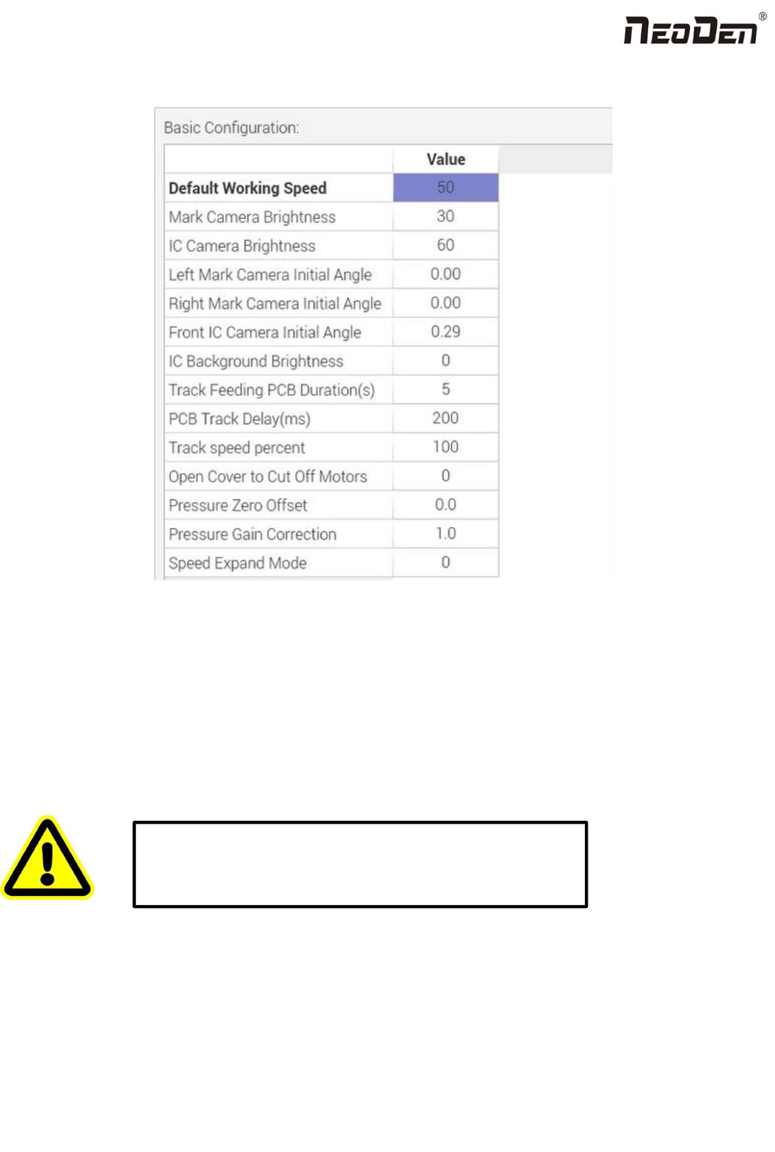
Fig: Basic Configuration
Default Working Speed: this is adopted by the placement speed in the mounting interface
Mark Camera Brightness and IC Camera Brightness: they are the default value when coming out from the factory. The
default value for Mark Camera Brightness is 30,and for IC Camera Brightness is 40. They can be adjusted according to the
real situation.
Left Mark Camera Initial Angle,Right Mark Camera Initial Angle,Front IC Camera Initial Angle and Back IC
Camera Initial Angle:
Track Feeding PCB Duration(S): track forward to the conveyor and sending the signal,the duration of waiting for the
PCB feeding
Open Cover to Cut Off Motors: this is to prevent any body damage during picking and placing. if set value 0, in the
mounting process when open the cover, the machine will turn to Step mode to do the mounting, due to the safety
Warning: the values are already set up before shipping, no extra
adjustment is required. There is a risk to lead to malfunctional
condition, please kindly contact technical engineer before
operation.

43
Zhejiang Neoden Technology Co., Ltd
consideration; if set value 0, and open the cover in the mounting process, the machine continues mounting but with lower
speed as 20.
10. First trial and test
10.1 Program first dry run
Usually we would suggest you to have a dry run (no components are loaded) before production test. After it goes smoothly,
you can start to produce few boards.
10.2 First production test
1 Make a programming file
2 Test the file to pick and place components to finish one board.
10.3 Component Inspection
Inspection items
●Check if the specification, direction, polarity of components is aligned with what they should be.
●Whether the components are damaged or the pins are distorted.
●Whether the component is off beyond allowance.
The inspection methods vary from the equipment that you have.
Except visual inspection, all of amplifier, microscope, online or offline AOI equipment can be applied if the pitch of IC is
quite small to check.
Inspection Standard
Please follow SOP to do inspection or any other general standards (IPC Standard and SJ/T10670-1995 SMT General
Technical Requirements). Adjust the programming file according to the placement effect after the first production test.
1. If there are any specification, direction and polarity issues, please do the adjustment according to the process file.
2. If there is any deviations of the chip placement, please do the adjustment by following two methods:
(1) If the placement effects of all components are off in the same direction, it would be the fiducial issues. Please adjust
the coordinates of fiducials according to its value of deviation.
(2) If there are several components off beyond allowance, you’d better adjust their coordinates on working file with
down-looking camera. If there are couple of issues occur during test, some other points need to be considered.
3. Frequent pickup failure. Some suggestions are listed below
(1) The pick height is inappropriate, please revise the value after an inspection or a pick-test
(2) The pick offset needs an adjustment, it should be aligned with the center of component reel slot rather than that of
component.
(3) Due to peel strength or installation issue of wasted film, the film on tape won’t be peeled completely