DR4900 用户手册_Full version.pdf - 第11页
Figure 5 Cell adapter installation 4.4.2 Install the light shield The light shield keeps light out of cell compartment 2. Install the light shield in the cell compartment 2 before a measurement is started in cell compart…
The Ethernet port sends data to local networks or LIMS systems. Use a shielded cable (e.g., STP,
FTP, S/FTP) that is 20 m (65.6 ft) or less.
4.4 Cell compartments and adapters
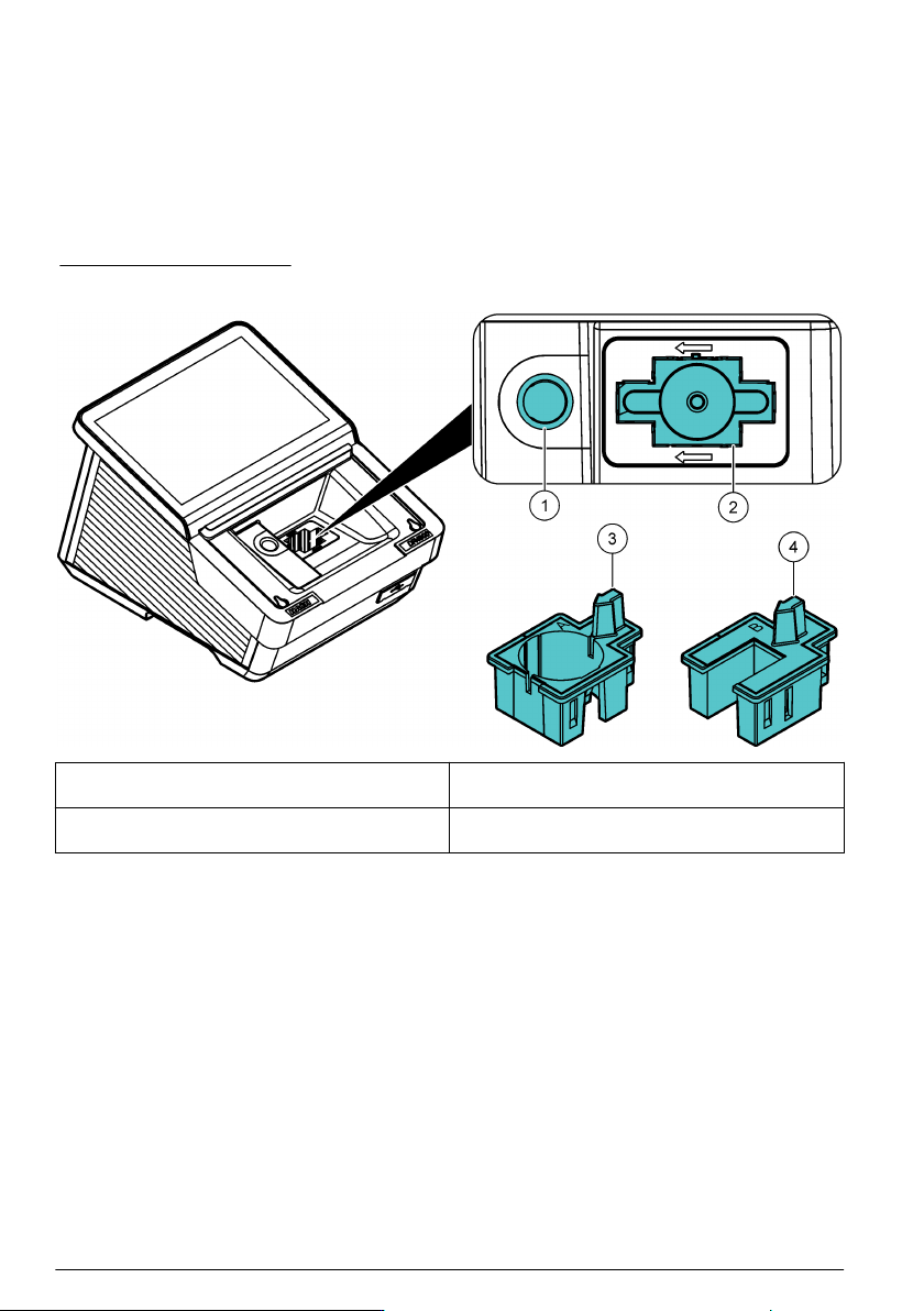
The instrument has two cell compartments. Refer to Figure 4. Only one sample cell can be used at a
time.
Cell compartment 1—Barcode, temperature and turbidity detection for 13-mm round sample cells
Cell compartment 2—50-mm and 1-inch rectangular sample cells and 1-inch flow sample cells, cell
adapter A and cell adapter B
Figure 4 Cell compartment
1 Cell compartment 1: round sample cells 3 Cell adapter A: 10-mm rectangular sample cells, 1-
inch round sample cells and AccuVac
®
vials
2 Cell compartment 2: 50-mm and 1-inch rectangular
sample cells and 1-inch flow sample cells
4 Cell adapter B: 30-mm vials (China only)
4.4.1 Install the cell adapter
Install the applicable cell adapter for the sample cell type as follows:
1. Open the cell compartment.
2. Install the cell adapter in cell compartment 2 so that the arrow on the cell adapter points to the
left. Refer to Figure 5.
Note: The arrow on top of the cell adapter shows the direction of the light beam path.
10
English
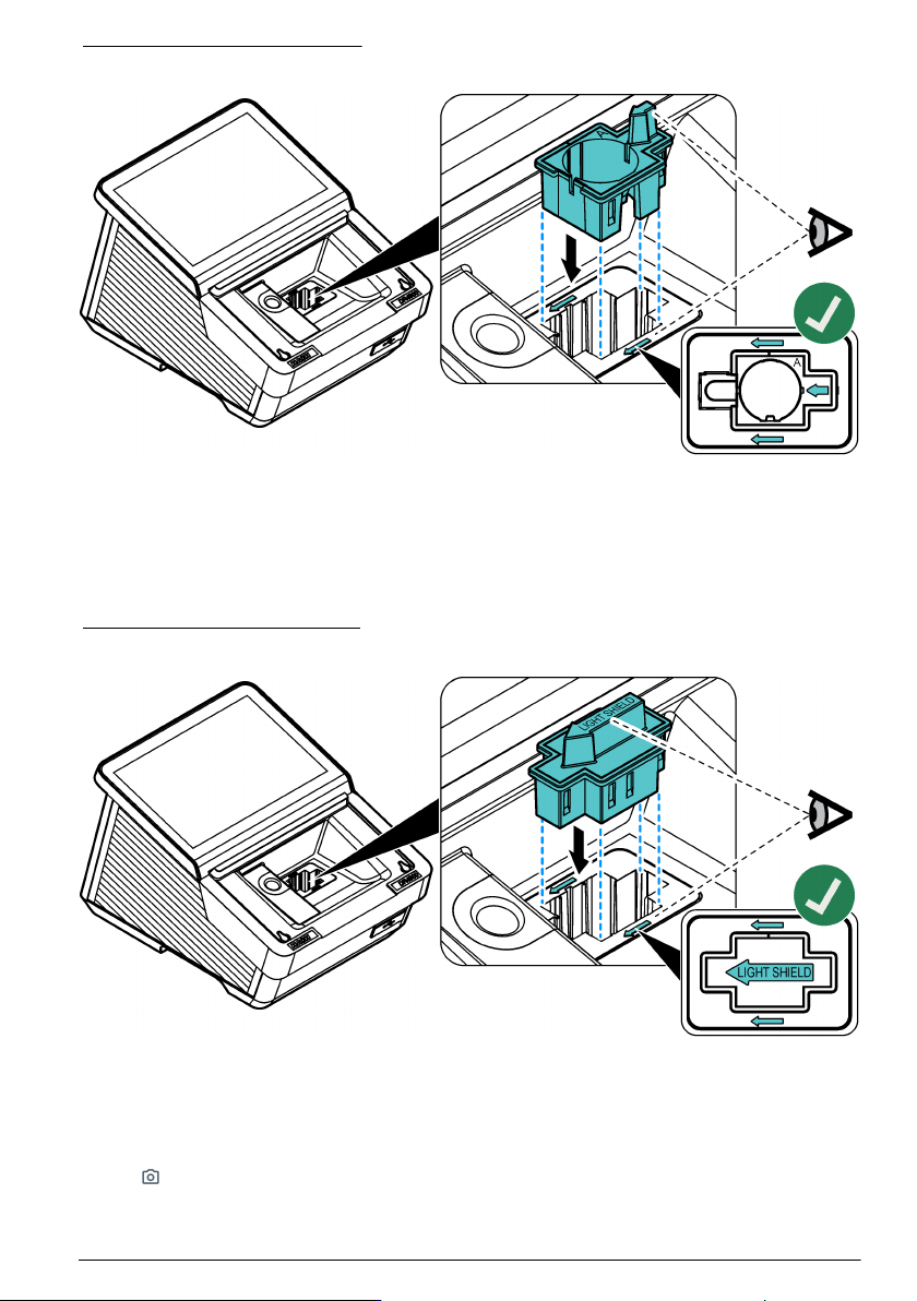
Figure 5 Cell adapter installation
4.4.2 Install the light shield
The light shield keeps light out of cell compartment 2.
Install the light shield in the cell compartment 2 before a measurement is started in cell compartment
1. Make sure that the arrow on the light shield points to the left. Refer to Figure 6.
The instrument is shipped with the light shield installed. Remove the light shield before cell
compartment 2 is used.
Figure 6 Light shield installation
4.5 Install the camera (optional)
1. Install the supplied camera on top of the camera holder. Tighten the screw. Refer to step 1 of
Figure 7.
2. Connect the supplied USB cable to the camera and the DR4900.
The shows in the menu bar. Refer to Figure 8 on page 13.
English
11
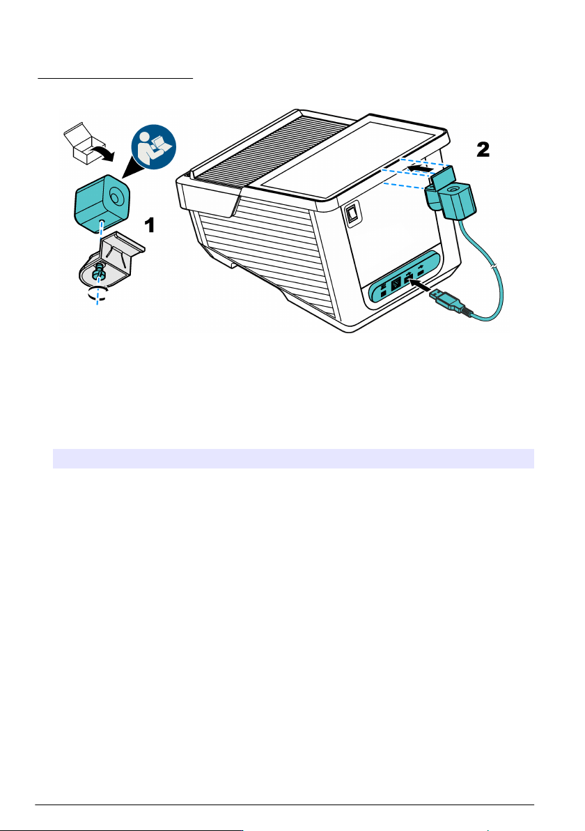
3. Install the camera holder with the camera on the backside above the accent light. Refer to step
2 of Figure 7.
4. Refer to Use the camera (optional) on page 28 for camera instructions.
Figure 7 Camera installation
Section 5 Startup assistant
When the instrument is set to on for the first time, a start-up assistant starts.
1. The startup procedure takes about 45 seconds. The startup procedure is complete when a
melody is heard.
2. Select the options:
Option Description
Language Select the applicable language from the list.
Date & time Set the date and time.
Display Move the slider to adjust the brightness of the display.
Ethernet and Wi-Fi
connection
Note: An Ethernet cable or Wi-Fi dongle must be connected.
Configure the Ethernet parameters to connect the instrument to a network or
send data to a PC.
Security Set a password for operator access.
Note: Push Next to save the password.
3. Push Done to complete the setup.
The instrument starts when the instrument is set to on with a system check. The system check
examines the lamp, the filter adjustment, the λ-calibration, the air measurement and the voltage
of the instrument.
Note: If the lid is not closed during the system check, the system check will stop.
The accent light will pulsate blue during the startup. Refer to Table 5 on page 20. Then, the
measurement screen will show.
Section 6 User interface and navigation
Figure 8 shows an overview of the main screen. Refer to Icon description list on page 13 for
descriptions of icons that show on the display.
The instrument display is a touchscreen. Only use a clean, dry finger tip to navigate through the
menu of the touchscreen.
12
English