DR4900 用户手册_Full version.pdf - 第9页
• In a location that is not dusty, humid or wet. Always keep the surface of the instrument, the cell compartment and all accessories clean and dry. 4.2 Startup W A R N I N G Fire hazard. Only use the supplied benchtop po…
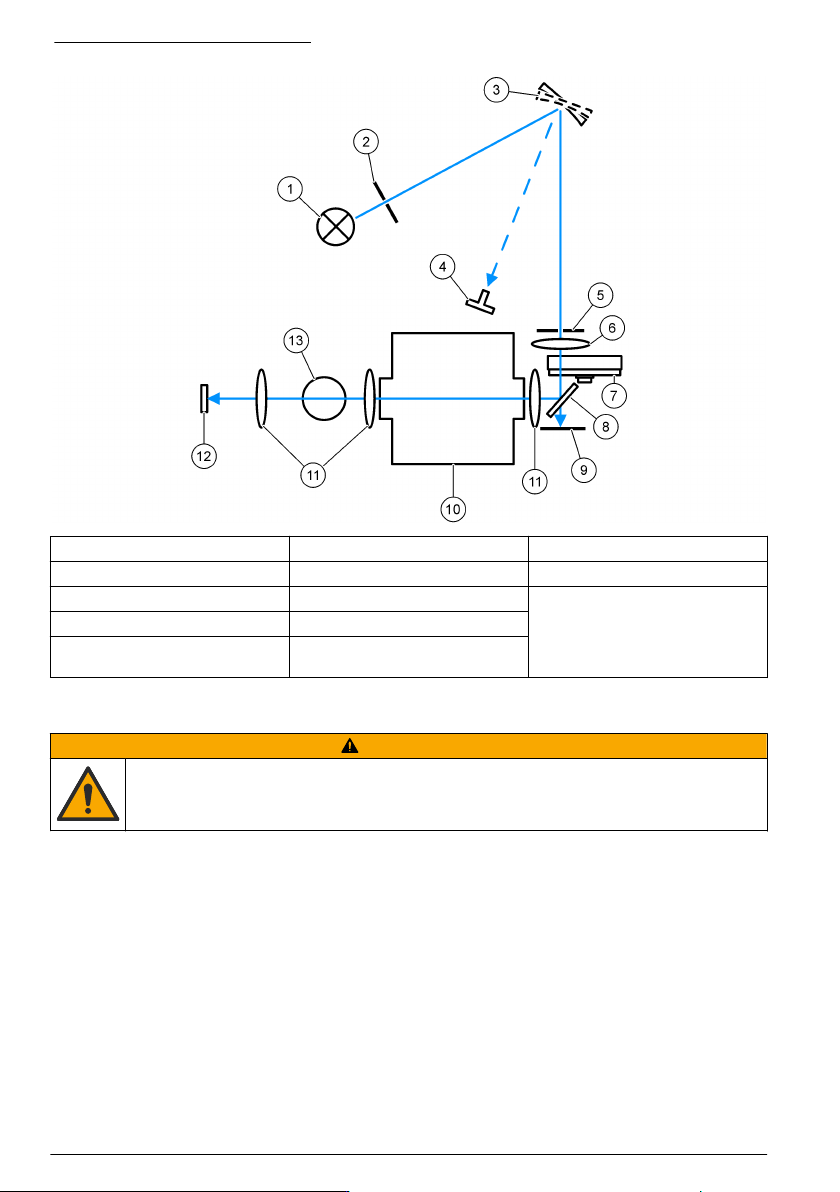
Figure 2 DR4900 light beam path
1 Halogen lamp 6 Lens 11 Lens
2 Lamp opening 7 Filter wheel 12 Measurement element
3 Grating 8 Beam splitter mirror 13 Cell compartment 1 for round
cells
4 Grating angle indicator 9 Reference element
5 Exit slit 10 Cell compartment 2 for
rectangular cells
Section 4 Installation
C A U T I O N
Multiple hazards. Only qualified personnel must conduct the tasks described in this section of the
document.
4.1 Operating environment
Install the instrument:
• On a level, rigid surface with sufficient load bearing capacity. Do not put objects below the
instrument.
• In a location without direct sunlight.
• Away from very high temperatures caused by sunlight, heaters or other sources.
• On a surface so that the power cord is not bent and the instrument can be easily set to off with the
power switch.
• In an ambient temperature of 10–40 °C (50–104 °F).
• In relative humidity of less than 80%. Do not let moisture collect on the instrument.
• Away from high humidity or chemically contaminated air or instrument damage will occur.
• With a minimum clearance of 15 cm around the instrument. Damage will occur if the instrument
becomes too hot.
8
English
• In a location that is not dusty, humid or wet. Always keep the surface of the instrument, the cell
compartment and all accessories clean and dry.
4.2 Startup
W A R N I N G
Fire hazard. Only use the supplied benchtop power supply LZV844.
C A U T I O N
Electrical shock and fire hazards. Make sure that the supplied cord and non‐locking plug meet the
applicable country code requirements.
N O T I C E
Always set the power switch to off before the power supply is connected to a electrical outlet or damage to the
instrument can occur.
N O T I C E
To prevent damage to the electronics and mechanics of the instrument, wait approximately 20 seconds after the
power switch is set to off before the power switch is set to on again.
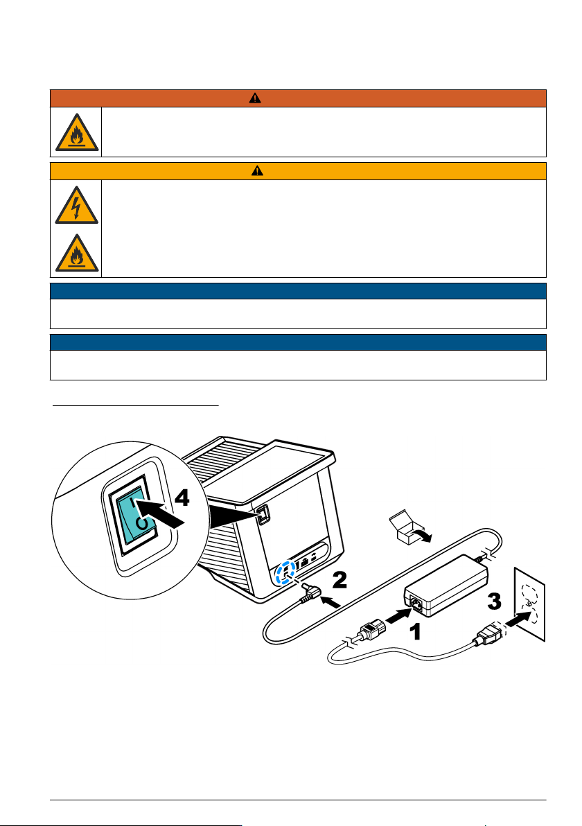
Connect the power supply to the instrument. Refer to Figure 3.
Figure 3 AC power connection
4.3 Interfaces
The instrument has four USB ports and one Ethernet port. Refer to Figure 1 on page 7.
A USB hub connected to power can be used to connect multiple USB accessories at a time.
Note: Make sure that the USB cable is 3 m (9.8 ft) or less.
Send the saved data through the USB port to a printer. Use the USB-serial converter cable to
connect the instrument to a PC. Use the USB port to update the instrument software, export data and
certificates with a USB flash drive.
English
9
The Ethernet port sends data to local networks or LIMS systems. Use a shielded cable (e.g., STP,
FTP, S/FTP) that is 20 m (65.6 ft) or less.
4.4 Cell compartments and adapters
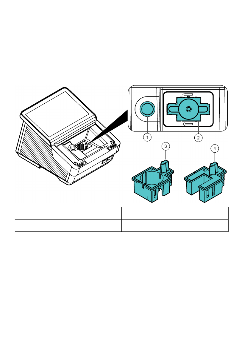
The instrument has two cell compartments. Refer to Figure 4. Only one sample cell can be used at a
time.
Cell compartment 1—Barcode, temperature and turbidity detection for 13-mm round sample cells
Cell compartment 2—50-mm and 1-inch rectangular sample cells and 1-inch flow sample cells, cell
adapter A and cell adapter B
Figure 4 Cell compartment
1 Cell compartment 1: round sample cells 3 Cell adapter A: 10-mm rectangular sample cells, 1-
inch round sample cells and AccuVac
®
vials
2 Cell compartment 2: 50-mm and 1-inch rectangular
sample cells and 1-inch flow sample cells
4 Cell adapter B: 30-mm vials (China only)
4.4.1 Install the cell adapter
Install the applicable cell adapter for the sample cell type as follows:
1. Open the cell compartment.
2. Install the cell adapter in cell compartment 2 so that the arrow on the cell adapter points to the
left. Refer to Figure 5.
Note: The arrow on top of the cell adapter shows the direction of the light beam path.
10
English