00193411-02.pdf - 第101页
User Manual SIPLAC E HS-60 4 Setting up the placement system Software version SR.503.xx 07/2003 US Edition 4.1 Transport dimensions 101 4 Setting up the placement system 4.1 T ransport dime nsions The pla cement s ystem …
3 Technical data User Manual SIPLACE HS-60
3.10 Overview of the modules - PCB conveyor Software version SR.503.xx 07/2003 US Edition
100
User Manual SIPLACE HS-60 4 Setting up the placement system
Software version SR.503.xx 07/2003 US Edition 4.1 Transport dimensions
101
4 Setting up the placement system
4.1 Transport dimensions
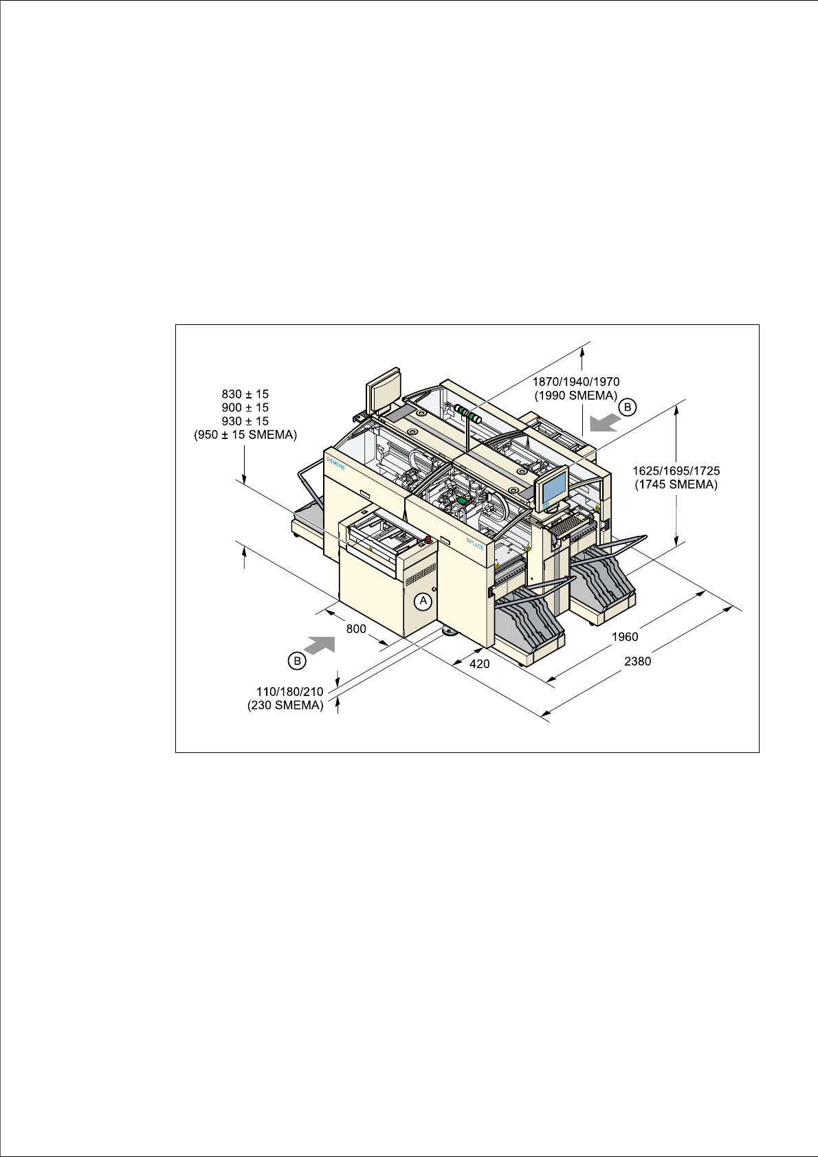
The placement system mounting kit (A) on the input side can be dismantled for transportation pur-
poses. This will reduce the width of the machine from 2380 mm to 1960 mm.
4
Fig. 4.1 - 1 Dimensions of the placement system during transportation and setting up
in millimeters
4
A Mounting kit, which can be dismantled for transportation purposes
B Points for attaching the fork-lift truck (fork length: 2500 mm)
The PCB conveyor height is 830 mm ± 15 mm or 95
0mm ± 15 mm in accordance with the SMEMA
standard. The height specification for the machine will change accordingly.

4 Setting up the placement system User Manual SIPLACE HS-60
4.1 Transport dimensions Software version SR.503.xx 07/2003 US Edition
102
4.1.1 Transport configuration and transportation
The following components are not installed when the placement system is delivered from the fac-
tory:
– keyboards
–monitors
– fault indicator lamp and
– component trolley
Æ Install the dismantled components for commissioning.
Æ Use a fork-lift truck to transport the placement system:
– minimum fork length 2000 mm if the mounting kit is dismantled.
– minimum fork length 2500 mm if the mounting kit is dismantled.
Æ Attach the fork-lift truck only at the indicated points.
4.1.2 Quality of the foundation
Æ Ensure that
– you set up the placement system on a firm and non-vibrating foundation.
– the load bearing capacity per unit area of the foundation is greater than 1000 kg/m².
4.1.3 Compressed air supply
– The pressure of the compressed air supply must be between 0.65 MPa and 1.0 MPa (6.5 bar
and 10 bar).
– The compressed air must conform to the specification (see Section 3.4
from page 79).
This can be achieved with
– oil-free compressors, e.g. Atlas, Copco type ZR4
– compressed air washer/driers
– micro-filters, series X, e.g. from Zander
4.1.4 Main power supply
– The power socket must be fused. The fuse ratings are:
3x32A for 3x204VAC 4
3x32A for 3x230VAC 4