00193411-02.pdf - 第94页
3 Technical data User Manual SIPLACE HS-60 3.9 Overview of the modules - vision modules Software version SR .503.xx 07/2003 US Edition 94 3.9.2 PCB vision modul e (standard camera) 3.9.2.1 S tructure 3 Fig. 3.9 - 2 PCB v…
User Manual SIPLACE HS-60 3 Technical data
Software version SR.503.xx 07/2003 US Edition 3.9 Overview of the modules - vision modules
93
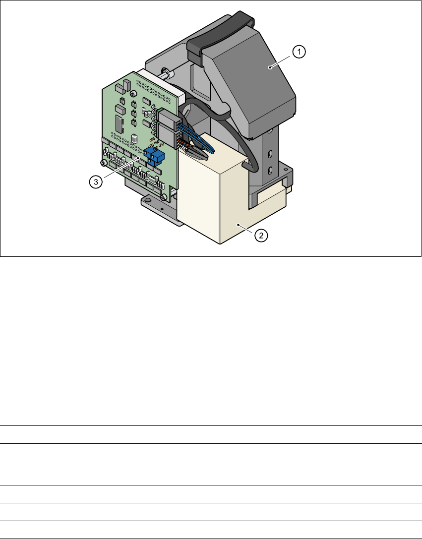
3.9.1 Component vision module (standard camera) on the 12-segment
Collect&Place head
3.9.1.1 Structure
3
Fig. 3.9 - 1 Component vision module (standard camera) on the 12-segment Collect&Place head
3
(1)Component camera, lens and illumination
(2)Camera amplifier
(3)Illumination control
3.9.1.2 Technical data
3
Component dimensions 0.5 mm x 1.0 mm to 18.7 mm x 18.7 mm
Range of components 0402 to PLCC44
including BGA, µBGA, flip-chip, TSOP, QFP
PLCC, SO to SO32, DRAM
Min. lead pitch 0.5 mm
Field of vision 24 mm x 24 mm
Method of illumination Front-lighting (3 levels, programable as required)
3 Technical data User Manual SIPLACE HS-60
3.9 Overview of the modules - vision modules Software version SR.503.xx 07/2003 US Edition
94
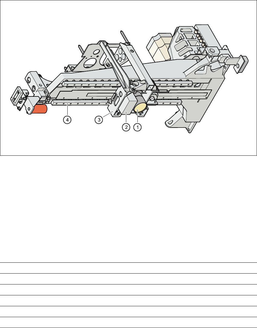
3.9.2 PCB vision module (standard camera)
3.9.2.1 Structure
3
Fig. 3.9 - 2 PCB vision camera (standard), gantry - view from below
3
(1) PCB camera, lens and illumination
(2) Camera amplifier
(3) Head mount
(4) Gantry
3.9.2.2 Technical data
Fiducials Up to 3 per placement program
Library size Up to 255 fiducial types - system fiducials ≥ 249
Image processing Geometric alignment
Method of illumination Front-lighting
Recognition time per fiducial/bad fiducial 0.4 s
Field of vision 5.7 mm x 5.7 mm
User Manual SIPLACE HS-60 3 Technical data
Software version SR.503.xx 07/2003 US Edition 3.10 Overview of the modules - PCB conveyor
95
3.10 Overview of the modules - PCB conveyor
3.10.1 Description
The placement machine is supplied with a single conveyor as standard. A dual conveyor is avail-
able as an option. The left or the right side of the PCB conveyor can be used as the stationary
side, as required.
For placement, the PCB is clamped from below. The distance between the top of the PCB and the
placement head thus remains unchanged for each PCB, and is no longer dependent on the thick-
ness of the PCB. The placement rate is thus also independent of the PCB thickness. The PCB
fiducial centering can also be optimized. Since the distance between the PCB surface and the
PCB camera remains the same, the PCB camera is always focussed on the PCB surface with the
same sharpness. The PCB fiducial contours are optimally mapped on the CCD chip of the PCB
camera.
The width of the circuit board conveyor is set and monitored by an integral control circuit. It can
be selected by calling up the program. The control circuit then actuates the stepping motors until
the desired width is reached. The width adjustment is therefore independent of other machine
components. 3
The transport height can be modified, thus allowing the machines to be integrated into lines with
a transport height of 830, 900, 930 or 950 mm. Communication between the PCB conveyors of
the individual systems is via the SIEMENS or SMEMA interface, as desired. The fixed transport
side can be located on the left or right for both the dual conveyor and the single conveyor. With
this conveyor, the fixed side can be easily switched from right to left and vice versa.
The circuit board conveyor is monitored and controlled with optical sensors. If the board has
reached placement area and passed the light barrier, it is braked. A laser light barrier determines
the position of the board. As soon as the circuit board has reached its target position, the con-
veyor belt is stopped and the board is clamped from below. 3