00193411-02.pdf - 第148页
6 Component handling User Manual SIPLACE HS-60 6.5 Used tape c utter Software version SR.503.xx 07/2003 US E dition 148
User Manual SIPLACE HS-60 6 Component handling
Software version SR.503.xx 07/2003 US Edition 6.5 Used tape cutter
147
The used tape channels (see item 1 in Fig. 6.5 - 3) are located in front of the feeders. They are
seated directly above the used tape cutter (see item 3 in Fig. 6.5 - 3
).
The tape is automatically guided through the used tape guide channel into the used tape cutter
below. There, the tape is shredded by the pneumatically-actuated cutting blade. The waste tape
passes via the used tape chute (see item 4 in Fig. 6.5 - 3
) into the reject bin on the component
trolley.
6
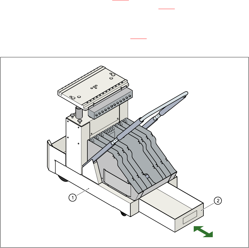
Fig. 6.5 - 4 Pull-out waste tape container in the component trolley
6
(1) Component trolley
(2) Pull-out waste tape container
6 Component handling User Manual SIPLACE HS-60
6.5 Used tape cutter Software version SR.503.xx 07/2003 US Edition
148
User Manual SIPLACE HS-60 7 Station extensions
Software version SR.503.xx 07/2003 US Edition 7.1 Nozzle changer for the 12-segment Collect&Place head
149
7 Station extensions
7.1 Nozzle changer for the 12-segment Collect&Place
head
7.1.1 Overview
The placement system is supplied as standard with 4 Collect&Place heads and 4 nozzle chang-
ers. As an option, a second nozzle changer can be installed for each Collect&Place head.
The nozzle changer consists of at least one, and up to five magazines, each with twelve nozzle
garages (see Fig. 7.1 - 1
). The magazines are seated on a common support. Each magazine is
centered using two parallel pins and fixed in place with clips.
7.1.2 Technical data
7
Nozzle changer for the Collect&Place head
Dimensions (length x width x height) 472.5 mm x 64 mm x 90 mm
Number of nozzle garages min. 12 / max. 60
Nozzle types 9 xx
Time required to open and close the locking plate < 200 ms
Pneumatic system Compressed air line 0.53 MPa (5.3 bar)