00193411-02.pdf - 第162页
7 Station extensions User Manual SIPLACE HS-60 7.4 PCB barcode Software version SR.503.xx 07/2003 US Edition 162 7.4 P CB barcode 7.4.1 Overvie w The PCB barcode reader is used to a utomatica lly rec ord and decode ba rc…

User Manual SIPLACE HS-60 7 Station extensions
Software version SR.503.xx 07/2003 US Edition 7.3 Dual conveyor
161
7.3.8.1 Technical data – dual conveyor
7
7
7
7.3.9 Preventive maintenance
The individual conveyor belts and the additional lifting table require the same maintenance as the
standard conveyor. Each conveyor belt must be maintained as described in the maintenance in-
structions.
Fixed conveyor side Right (standard), left (optional)
Max. component height 6 mm
PCB format 50 mm x 50 mm up to 368 mm x 216 mm (standard)
50 mm x 50 mm up to 368 mm x 242 mm (available upon
request)
Long board: PCB longer than 368 mm (option)
50 mm x 110 mm up to 610 mm x 216 mm
50 mm x 110 mm up to 610 mm x 242 mm (available upon
request)
PCB thickness 0.5 mm to 4.5 mm
Max. PCB warpage Up: 4,5 mm - PCB thickness
On bottom: 0.3 mm + PCB thickness
Clearance on PCB underside Standard: 25 mm
Option: max. 40 mm
PCB transport height 830 mm ± 15 mm (standard)
900 mm ± 15 mm (option)
930 mm± 15 mm (option)
950 mm ± 15 mm (SMEMA: optional)
Type of interface Siemens (standard)
SMEMA (optional)
Component-free PCB handling edge 3 mm
PCB changeover time 2.5 s
Conveyor mode Synchronous or asynchronous
Components on each conveyor Synchronous: different, asynchronous: same
PCB width on each conveyor Synchronous: different, asynchronous: same
Ink spot recognition Synchronous: not possible, asynchronous: possible
Automatic width adjustment Synchronous: not possible, asynchronous: possible
7 Station extensions User Manual SIPLACE HS-60
7.4 PCB barcode Software version SR.503.xx 07/2003 US Edition
162
7.4 PCB barcode
7.4.1 Overview
The PCB barcode reader is used to automatically record and decode barcodes on PCBs. The
PCB barcode reader sends the read data via its serial interface to the transport controller and then
for further processing to the machine controller via the CAN bus.
7
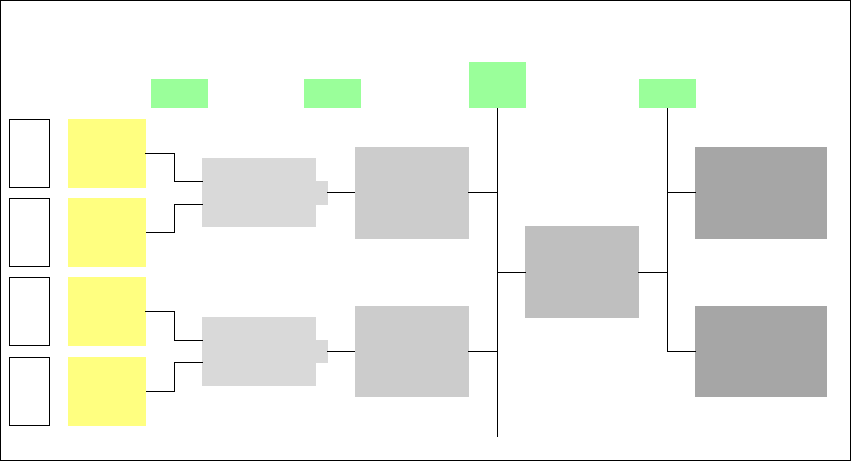
Fig. 7.4 - 1 PCB barcode block diagram
The PCB barcode readers are installed on the input side of the placement machine, above and
below the PCB conveyor, so that barcode labels on the topside and underside of the PCBs can
be read.
A maximum of four PCB barcode readers may be retrofitted in order to read the topside and un-
derside of the PCB on the transport track.
Device number
1
Barcode
reader
top
Distribution
board
Transport
controller,
right
Barcode
reader
bottom
2
3
Barcode
reader
top
Distribution
board
Transport
controller,
left
Barcode
reader
bottom
4
Machine
controller
Station
computer
SIPLACE Pro/
line computer
LAN
CAN
bus
V-24V-24
User Manual SIPLACE HS-60 7 Station extensions
Software version SR.503.xx 07/2003 US Edition 7.4 PCB barcode
163
7
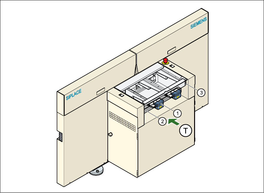
Fig. 7.4 - 2 PCB barcode reading head, profiled rails for PCB barcode reader ’bottom’/’top’
7
(1) PCB barcode reading head
(2) Profiled rail for ‘underside’ PCB barcode reader
(3) Profiled rail for ‘topside’ PCB barcode reader
(T) Direction of PCB transport
The PCB barcode readers are fixed to the top and bottom profiled rail using retainers. These can
be positioned as required on the profiled rails, and aligned with respect to the barcode labels. De-
pending on the position of the barcode strips, the barcode reader can be attached in a few simple
steps so that the strips can be read parallel to or across the PCB transport direction.