00193411-02.pdf - 第149页
User Manual SIPLAC E HS-60 7 Station extensions Software vers ion SR.503.xx 07/2003 US Edit ion 7.1 Nozzle changer f or the 12-segm ent Collect&Place head 149 7 S t ation extensions 7.1 Nozzle changer for the 1 2-seg…
6 Component handling User Manual SIPLACE HS-60
6.5 Used tape cutter Software version SR.503.xx 07/2003 US Edition
148

User Manual SIPLACE HS-60 7 Station extensions
Software version SR.503.xx 07/2003 US Edition 7.1 Nozzle changer for the 12-segment Collect&Place head
149
7 Station extensions
7.1 Nozzle changer for the 12-segment Collect&Place
head
7.1.1 Overview
The placement system is supplied as standard with 4 Collect&Place heads and 4 nozzle chang-
ers. As an option, a second nozzle changer can be installed for each Collect&Place head.
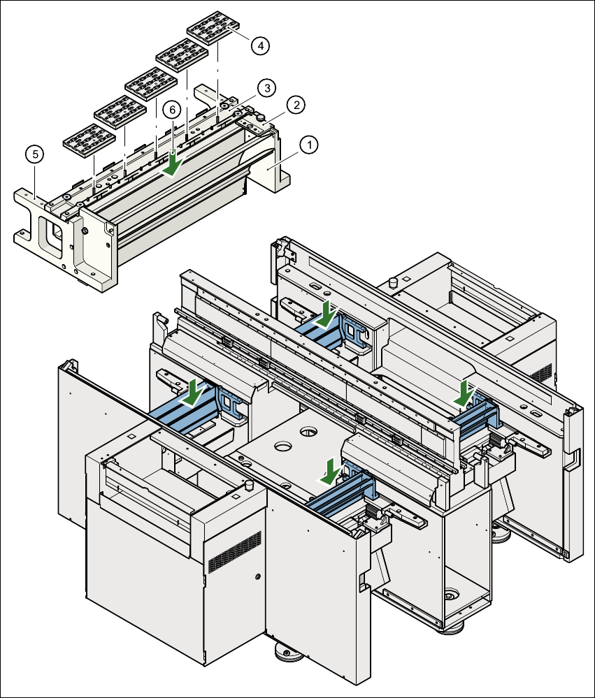
The nozzle changer consists of at least one, and up to five magazines, each with twelve nozzle
garages (see Fig. 7.1 - 1
). The magazines are seated on a common support. Each magazine is
centered using two parallel pins and fixed in place with clips.
7.1.2 Technical data
7
Nozzle changer for the Collect&Place head
Dimensions (length x width x height) 472.5 mm x 64 mm x 90 mm
Number of nozzle garages min. 12 / max. 60
Nozzle types 9 xx
Time required to open and close the locking plate < 200 ms
Pneumatic system Compressed air line 0.53 MPa (5.3 bar)
7 Station extensions User Manual SIPLACE HS-60
7.1 Nozzle changer for the 12-segment Collect&Place head Software version SR.503.xx 07/2003 US Edition
150
7
Fig. 7.1 - 1 Position of the nozzle changer
(1) Used tape channel
(2) Nozzle discarding device
(3) Nozzle changer
(4) Nozzle magazines
(5) Location for optional 2nd nozzle changer
(6) Reject bin for discarded nozzles