00193411-02.pdf - 第76页
3 Technical data User Manual SIPLACE HS-60 3.2 The line conc ept Software version SR. 503.xx 07/2003 US Edition 76 3.2 The line conc ept 3.2.1 Overvie w The pla cement s ystem can be link ed to in put and output s tation…

User Manual SIPLACE HS-60 3 Technical data
Software version SR.503.xx 07/2003 US Edition 3.1 Description of the machine
75
3.1.1 Technical data - machine overview
3
*) The HS-60 can be equipped to place 0201 components. Please consult the factory if you require this.
**) With this conveyor the circuit board is clamped from the underside. The distance from the top of the PCB to the
placement head thus remains constant and the placement rate is independent of the PCB thickness.
Placement procedure Collect&Place
Component range
*)
Components - dimensions
Max. component height
From 0201 to PLCC44, SO32, DRAM
From 0.6 mm x 0.3 mm to 18.7 mm x 18.7 mm
6mm
Max. placement rate 60,000 comp/h
12-segment Collect&Place head
Angular accuracy
Placement accuracy
± 0.70°/ 4 sigma
80 µm / 4 sigma with standard component camera
75 µm / 4 sigma with DCA camera (gantry 4)
PCB format
Single conveyor (length x width)
Dual conveyor (length x width)
50 mm x 50 mm up to 368 mm x 460 mm (standard)
50 mm x 50 mm up to 368 mm x 508 mm (available upon
request)
Long board: PCB longer than 368 mm (option)
50 mm x 110 mm up to 610 mm x 460 mm
50 mm x 110 mm up to 610 mm x 508 mm (available upon
request)
50 mm x 50 mm up to 368 mm x 216 mm (standard)
50 mm x 50 mm up to 368 mm x 242 mm (available upon
request)
Long board: PCB longer than 368 mm (option)
50 mm x 110 mm up to 610 mm x 216 mm
50 mm x 110 mm up to 610 mm x 242 mm (available upon
request)
PCB thickness 0.5 mm to 4.5 mm
PCB changeover time 2.5 sec
Transport heights 830 mm (standard)
900 mm, 930 mm, 950 mm (option)
Conveyor interface SIEMENS (standard)
SMEMA, mechanical and electrical specification (option)
Feeder capacity 144 8 mm tracks
Component supply
Types of feeder
CO trolley (see chapter 6
)
Component tapes, bulk cases, surftapes (see chapter 6
)
Connection Inline or stand alone
Space required 7.5 m² / module

3 Technical data User Manual SIPLACE HS-60
3.2 The line concept Software version SR.503.xx 07/2003 US Edition
76
3.2 The line concept
3.2.1 Overview
The placement system can be linked to input and output stations, screen printing systems, solder-
ing ovens, and other automatic placement systems from the SIPLACE family. All SIPLACE mod-
ules are provided with the necessary data by the UNIX line computer or the SIPLACE Pro
computer as appropriate. The placement system can also be linked to a higher level data process-
ing system through the use of suitable interfaces.
3.2.2 Technical data – line concept
3
System SIPLACE placement lines
Modules SIPLACE HF / SIPLACE HS-60 / SIPLACE HS-50 /
SIPLACE 80 S-20 / SIPLACE S-23 HM
SIPLACE 80 F4 / SIPLACE F5 / SIPLACE F5 HM,
SIPLACE S-25HM / S-27 HM
Peripherals Input/output stations
Screen printers
Soldering ovens
Inspection stations, etc.
Component range From 0201
PCB conveyor Automatic width adjustment
PCB format (length x width) 50 mm x 50 mm to 508 mm x 460 mm
(2" x 2" to 20" to 18")
Placement rate Depends how modules are connected in series
Space required 4 m² / SIPLACE S/F-module
7,5 m² / SIPLACE HS-module
User Manual SIPLACE HS-60 3 Technical data
Software version SR.503.xx 07/2003 US Edition 3.3 Connection data for the placement system
77
3.3 Connection data for the placement system
3.3.1 Electrical and pneumatic connection points on the placement system
3
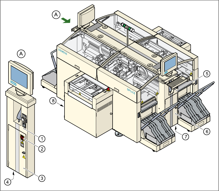
Fig. 3.3 - 1 Electrical and pneumatic connection points on the placement system
3
(1)Operator panel, on the left
(2)Main power switch
(3)Safety door to the power supply unit
(4)Hole for power cable feed-in
(5)Operator panel, on the right
(6)Safety door to the compressed air unit
(7)Hole for compressed air line feed-in
(8)LAN connection on the station computer